EasyManuals Logo

GE LOGIQ P5 Service Manual

GE LOGIQ P5
532 pages
To Next Page IconTo Next Page
To Previous Page IconTo Previous Page
Page #291 background imageLoading...
Page #291 background image
GE HEALTHCARE
DIRECTION 5394141, REVISION 5 LOGIQ™ P5 SEVICE MANUAL
Section 8-2 - DISASSEMBLY/RE-ASSEMBLY 8-45
8-2-11 Freeze key assy
8-2-11-1 Tools
Common pilIips screwdrivers
8-2-11-2 Preparations
Shut down the system and switch off the main breaker.
8-2-11-3 Removal procedure
1.) Remove the Main Keyboard Assy. Refer to the 8-2-7 "Main Keyboard Assy" on page 8-37.
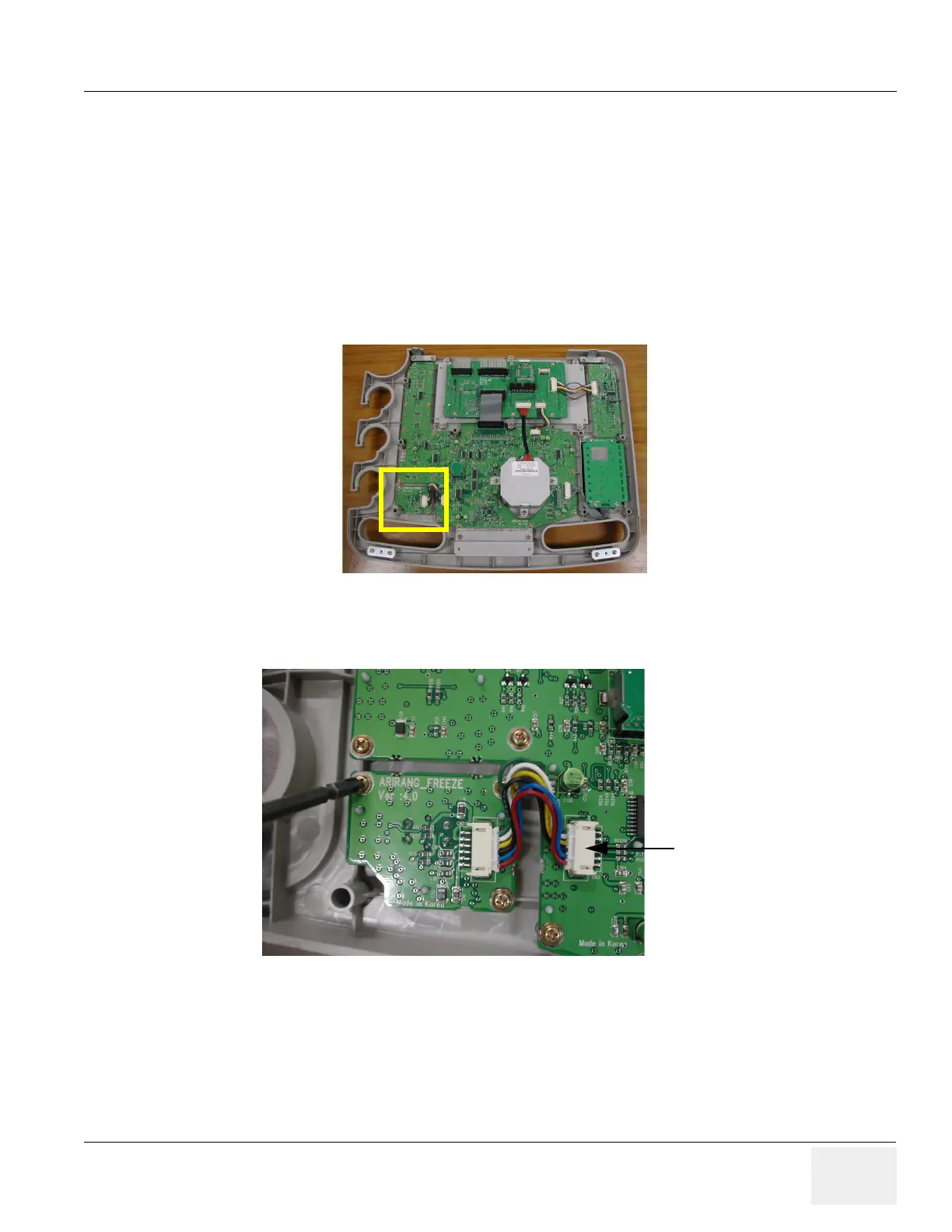
2.) Remove the 3 screws (1-3) and disconnect 1 cable.
Figure 8-77 Freeze Key in the main keyboard
Figure 8-78 Freeze Key connector
connector
1
1
2
3

Table of Contents

Other manuals for GE LOGIQ P5

Questions and Answers:

Question and Answer IconNeed help?

Do you have a question about the GE LOGIQ P5 and is the answer not in the manual?

GE LOGIQ P5 Specifications

General IconGeneral
Power Supply100-240VAC, 50/60Hz
Display15" LCD
Doppler ModesColor Doppler, Power Doppler
Imaging ModesB-Mode, M-Mode
ProbesConvex, Linear, Phased Array
ApplicationsAbdominal, Vascular, Cardiac, OB/GYN, Small Parts, Musculoskeletal
ConnectivityDICOM, USB, Ethernet
Probe Connectors3
PortabilityMobile
Operating Temperature10°C to 40°C
Relative Humidity30%

Related product manuals