GE HEALTHCARE
DIRECTION 5394141, REVISION 5 LOGIQ™ P5 SEVICE MANUAL
5-16 Section 5-4 - Main Board Detail
5-4-3 SYSCONPM(SYSCONCM)
5-4-3-1 Overview
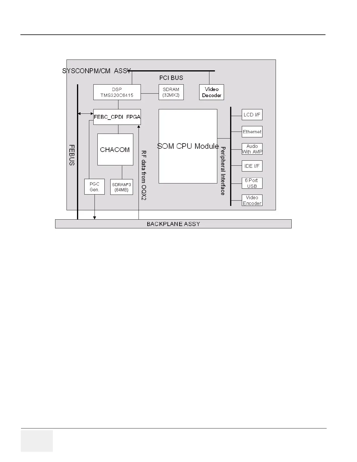
SYSCONPM(SYSCONCM) ASSY includes Mid processor and Back End Processor. DSP generate the
scan control data and the FEBC FPGA adjust the time and manipulate the FEBUS to control Front End
boards and APS/APS Pro. CPDI transfer the Image or Doppler data to the Image Ring buffer through
DSP. Finally the data goes to the SOM module to make displaying image or sound.
5-4-3-2 SYSTEM ON MODULE(SOM)
The SYSCONPM(SYSCONCM) Assy has System On Module PC(SOM) and PWA which is able to dock
SOM. In LOGIQ™ P5 system and LOGIQ™ P5 system, PWA is used the same one. But the System
On Module, which computes received Scan data, and interfaces the external peripheral devices (ex. B/
W printer, Digital Video Recorder etc.) are divided high grade for LOGIQ™ P5 and low grade for
LOGIQ™ A5 by it's CPU performance.
Figure 5-15 SYSCONPM(SYSCONCM) Block Diagram

 Loading...


