EasyManuals Logo

GE LOGIQ P5 Service Manual

GE LOGIQ P5
532 pages
To Next Page IconTo Next Page
To Previous Page IconTo Previous Page
Page #230 background imageLoading...
Page #230 background image
GE HEALTHCARE
DIRECTION 5394141, REVISION 5 LOGIQ™ P5 SEVICE MANUAL
7-22 Section 7-6 - LED Descriptions
7-6-4 APS/APS Pro Assy
NOTE: HVL+ and HVL- are not available for APS PRO.
The APS/APS Pro Assy is located at the No. 4 slot of the NEST Assy.
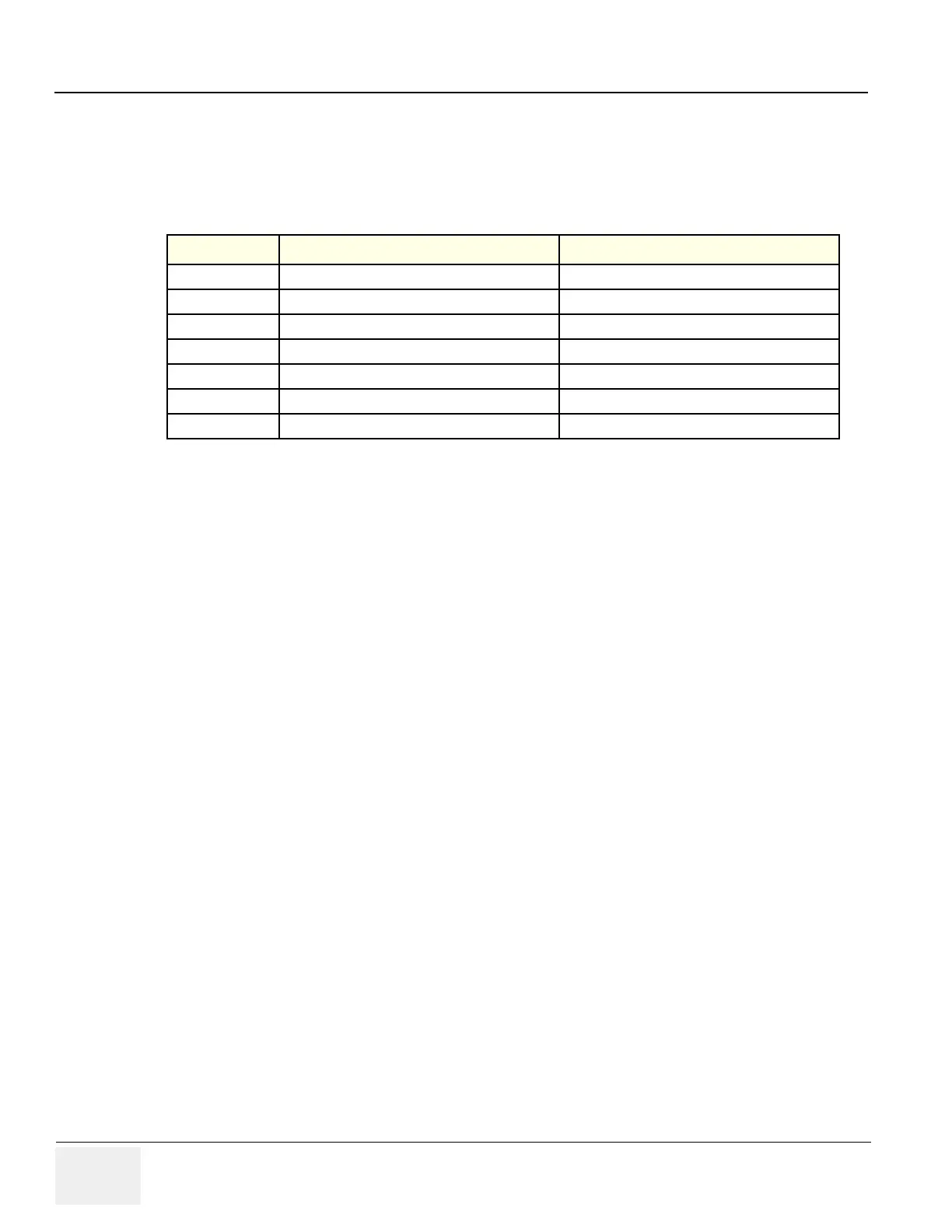
Table 7-11 LEDs on APS/APS Pro Assy
LED
Descriptions Normal State
DP5 (Top) Digital 5V output indicator Normally On
LP5 Live Power 5V output indicator Normally On
AP6 Analog 6V output indicator Normally On
DP33 Digital 3.3V output indicator Normally On
SHV+ SHV+ output indicator status indicator Normally On
HVL+ HVL+ level indicator Normally On in CFM mode or PW mode
HVH+ (Bottom) HVH+ level indicator Normally On in B mode

Table of Contents

Other manuals for GE LOGIQ P5

Questions and Answers:

Question and Answer IconNeed help?

Do you have a question about the GE LOGIQ P5 and is the answer not in the manual?

GE LOGIQ P5 Specifications

General IconGeneral
Power Supply100-240VAC, 50/60Hz
Display15" LCD
Doppler ModesColor Doppler, Power Doppler
Imaging ModesB-Mode, M-Mode
ProbesConvex, Linear, Phased Array
ApplicationsAbdominal, Vascular, Cardiac, OB/GYN, Small Parts, Musculoskeletal
ConnectivityDICOM, USB, Ethernet
Probe Connectors3
PortabilityMobile
Operating Temperature10°C to 40°C
Relative Humidity30%

Related product manuals