EasyManuals Logo

GE LOGIQ P5 Service Manual

GE LOGIQ P5
532 pages
To Next Page IconTo Next Page
To Previous Page IconTo Previous Page
Page #438 background imageLoading...
Page #438 background image
GE HEALTHCARE
DIRECTION 5394141, REVISION 5 LOGIQ™ P5 SEVICE MANUAL
8-192 Section 8-7 - Mechanical Option Installation instruction
8-7-9 Color Printer Fixture Middle installation - UP-D25MD Printer
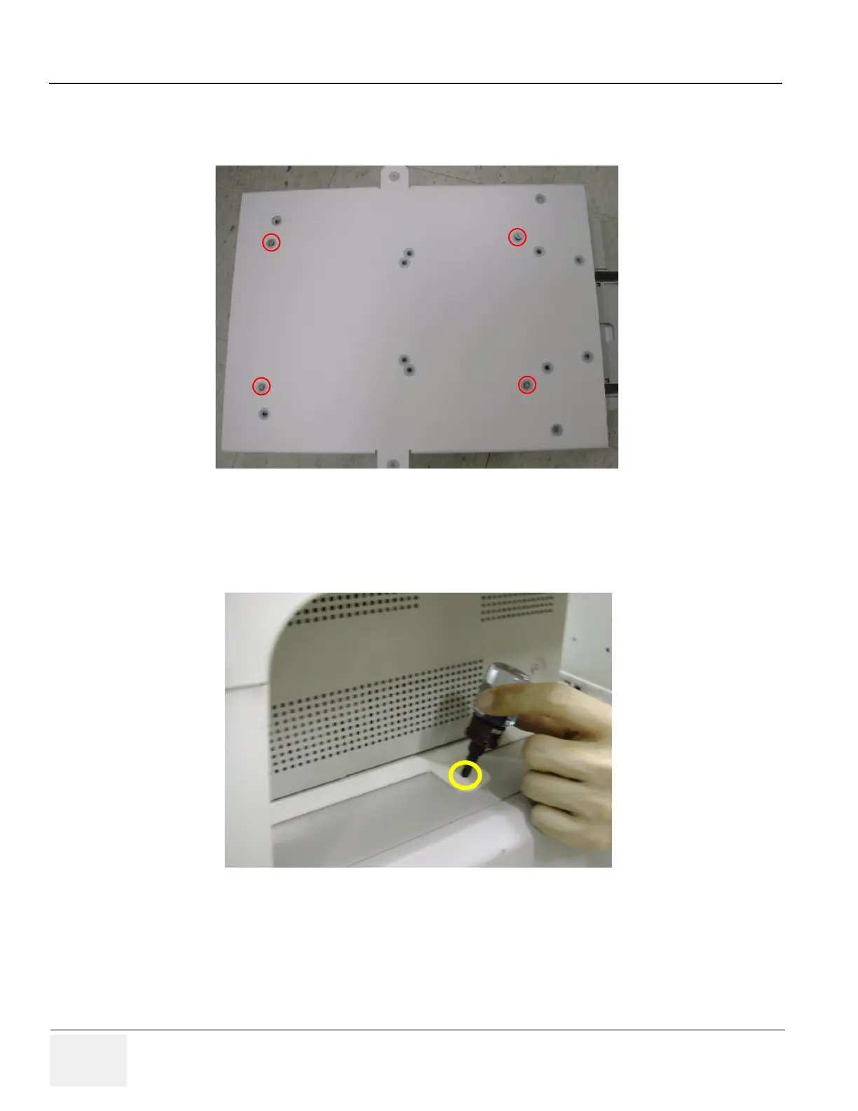
1.) Install color printer on the top of the base bracket by screw 4 screws(2306562, FH M3x6 YEL).
2.) Unscrew 2 existing screws from the middle cover.
3.) Screw 2 screws (5176744, BH M4x20 WHT) on each side of the system to fix the Color printer with
base bracket to the system.
Figure 8-274 Color Printer Fixture Middle installation
Figure 8-275 Color Printer Fixture Middle installation

Table of Contents

Other manuals for GE LOGIQ P5

Questions and Answers:

Question and Answer IconNeed help?

Do you have a question about the GE LOGIQ P5 and is the answer not in the manual?

GE LOGIQ P5 Specifications

General IconGeneral
Power Supply100-240VAC, 50/60Hz
Display15" LCD
Doppler ModesColor Doppler, Power Doppler
Imaging ModesB-Mode, M-Mode
ProbesConvex, Linear, Phased Array
ApplicationsAbdominal, Vascular, Cardiac, OB/GYN, Small Parts, Musculoskeletal
ConnectivityDICOM, USB, Ethernet
Probe Connectors3
PortabilityMobile
Operating Temperature10°C to 40°C
Relative Humidity30%

Related product manuals