EasyManuals Logo

GE LOGIQ P5 Service Manual

GE LOGIQ P5
532 pages
To Next Page IconTo Next Page
To Previous Page IconTo Previous Page
Page #322 background imageLoading...
Page #322 background image
GE HEALTHCARE
DIRECTION 5394141, REVISION 5 LOGIQ™ P5 SEVICE MANUAL
8-76 Section 8-2 - DISASSEMBLY/RE-ASSEMBLY
8-2-30 P3RLY / P2RLY Assy & P2RLY with Dummy
8-2-30-1 Tools
Common pilIips screwdrivers
8-2-30-2 Preparations
Shut down the system and switch off the main breaker.
8-2-30-3 Removal procedure
1.) Remove the side right cover. Refer to the 8-2-16 "Side Right Cover" on page 8-52.
2.) Remove the side left cover. Refer to the 8-2-15 "Side Left Cover" on page 8-51.
3.) Remove the Front Cover. Refer to the 8-2-17 "Front Cover" on page 8-53.
4.) Remove the ASIG Board. Refer to the 8-2-35 "ASIG Assy" on page 8-86.
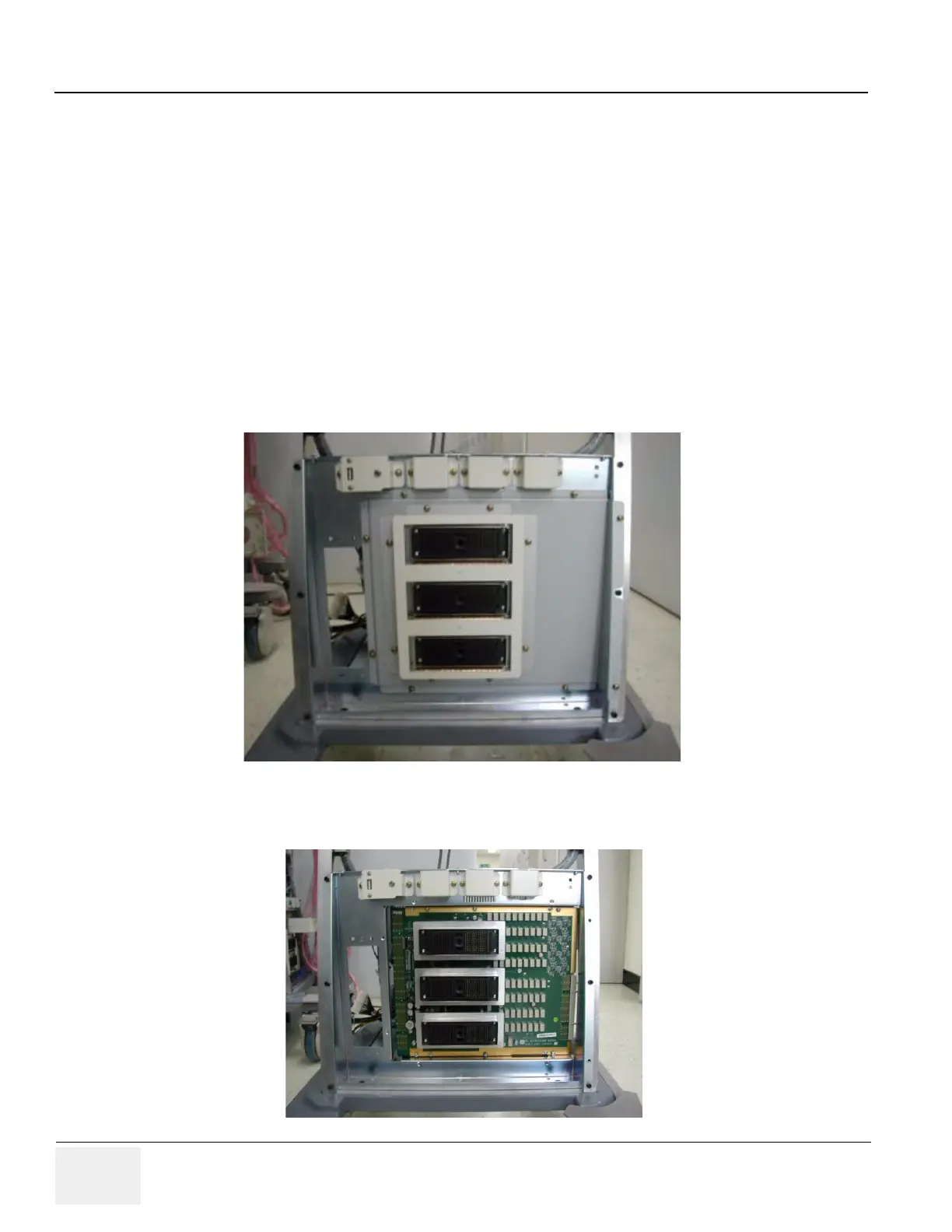
5.) Unscrew 8 screws (1-8) and remove the metal cover.
6.) Unscrew 6 screws (1-6) and remove the PCB.
Figure 8-111 RLY Cover
Figure 8-112 Screws of the RLY board
(8)
(7)
(6)
(5)
(4)
(3)
(2)
(1)
(1)
(2)
(3)
(4)
(5)
(6)

Table of Contents

Other manuals for GE LOGIQ P5

Questions and Answers:

Question and Answer IconNeed help?

Do you have a question about the GE LOGIQ P5 and is the answer not in the manual?

GE LOGIQ P5 Specifications

General IconGeneral
Power Supply100-240VAC, 50/60Hz
Display15" LCD
Doppler ModesColor Doppler, Power Doppler
Imaging ModesB-Mode, M-Mode
ProbesConvex, Linear, Phased Array
ApplicationsAbdominal, Vascular, Cardiac, OB/GYN, Small Parts, Musculoskeletal
ConnectivityDICOM, USB, Ethernet
Probe Connectors3
PortabilityMobile
Operating Temperature10°C to 40°C
Relative Humidity30%

Related product manuals