GE HEALTHCARE
DIRECTION 5394141, REVISION 5 LOGIQ™ P5 SEVICE MANUAL
Section 8-2 - DISASSEMBLY/RE-ASSEMBLY 8-75
8-2-29-3 Removal procedure (cont’d)
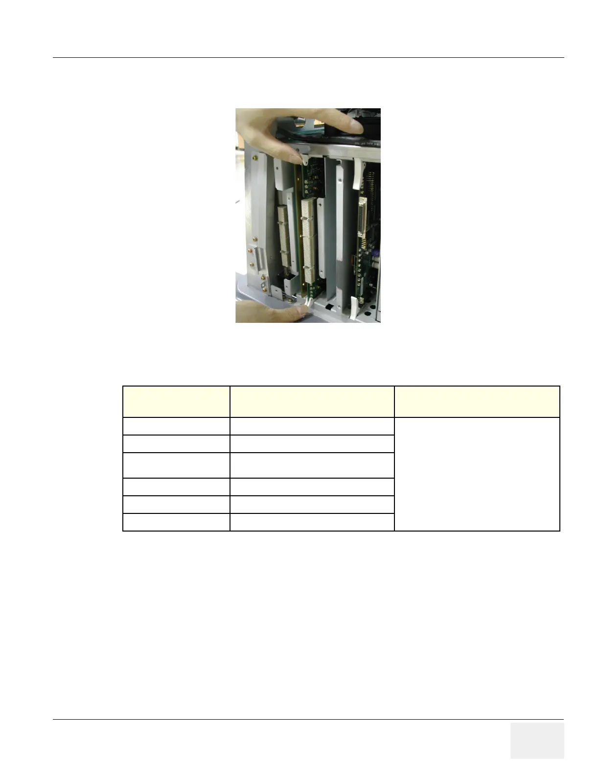
5.) Pull the CL1TRX Assy out.
6.) Perform the following functional tests. If all are successful, include the debrief script provided below.
8-2-29-4 Mounting Procedure
Install the new parts in the reverse order of removal.
Figure 8-110 Eject the CL1TRX(BL1TRX) Board
Table 8-30 Functional Tests
Service Manual
Section Functional Test / Diagnostic Test Debrief Script
Section 4-3-1
Power On/Boot Up
“Service Manual, Direction
5394141, Rev 1+, Section 8-2-29. Equipment
passed all required tests and is ready for use. “
Section 4-3-2
Power Off / Shutdown
Section 4-9-1
CL1TRX Assy / BL1TRX Assy Function
Validation Procedure
Section 4-3-4
System B/M-Mode Checks
Section 4-3-5
System CFM and PWD Checks
Section 10-5-2
Functional Checks (See Also Chapter 4)
 Loading...


