EasyManuals Logo

GE LOGIQ P5 Service Manual

GE LOGIQ P5
532 pages
To Next Page IconTo Next Page
To Previous Page IconTo Previous Page
Page #346 background imageLoading...
Page #346 background image
GE HEALTHCARE
DIRECTION 5394141, REVISION 5 LOGIQ™ P5 SEVICE MANUAL
8-100 Section 8-2 - DISASSEMBLY/RE-ASSEMBLY
8-2-44 DVD R/W Drive
8-2-44-1 Tools
Common pilIips screwdrivers
8-2-44-2 Preparations
Shut down the system and switch off the main breaker.
8-2-44-3 Removal procedure
1.) Remove the side left cover. Refer to the 8-2-15 "Side Left Cover" on page 8-51.
2.) Remove EMI L Cover. Refer to the 8-2-26 "EMI Cover L" on page 8-68.
3.) .) Remove the HDD assy. Refer to the 8-2-47 "SATA HDD Assy" on page 8-104.
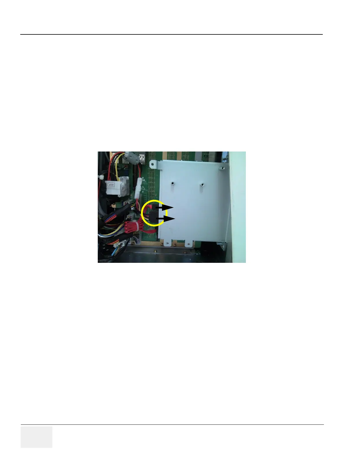
4.) Disconnect the HDD power cable and unscrew 4 screws of the HDD fixture bracket.
5.) Remove the Front Cover. Refer to the 8-2-17 "Front Cover" on page 8-53.
Figure 8-134 ODD SATA Power Cable and SATA cable of DVD Drive
SATA Cable
ODD SATA Power CAble

Table of Contents

Other manuals for GE LOGIQ P5

Questions and Answers:

Question and Answer IconNeed help?

Do you have a question about the GE LOGIQ P5 and is the answer not in the manual?

GE LOGIQ P5 Specifications

General IconGeneral
Power Supply100-240VAC, 50/60Hz
Display15" LCD
Doppler ModesColor Doppler, Power Doppler
Imaging ModesB-Mode, M-Mode
ProbesConvex, Linear, Phased Array
ApplicationsAbdominal, Vascular, Cardiac, OB/GYN, Small Parts, Musculoskeletal
ConnectivityDICOM, USB, Ethernet
Probe Connectors3
PortabilityMobile
Operating Temperature10°C to 40°C
Relative Humidity30%

Related product manuals