EasyManuals Logo

GE LOGIQ P5 Service Manual

GE LOGIQ P5
532 pages
To Next Page IconTo Next Page
To Previous Page IconTo Previous Page
Page #462 background imageLoading...
Page #462 background image
GE HEALTHCARE
DIRECTION 5394141, REVISION 5 LOGIQ™ P5 SEVICE MANUAL
8-216 Section 8-7 - Mechanical Option Installation instruction
8-7-18 Swivel Lock Caster Installation
NOTE: Both Front Casters and Rear Casters are swivel type in LOGIQ™ A5 but in LOGIQ™ A5, only
Front Casters are swivel type (Rear Casters are “Fixed” type).
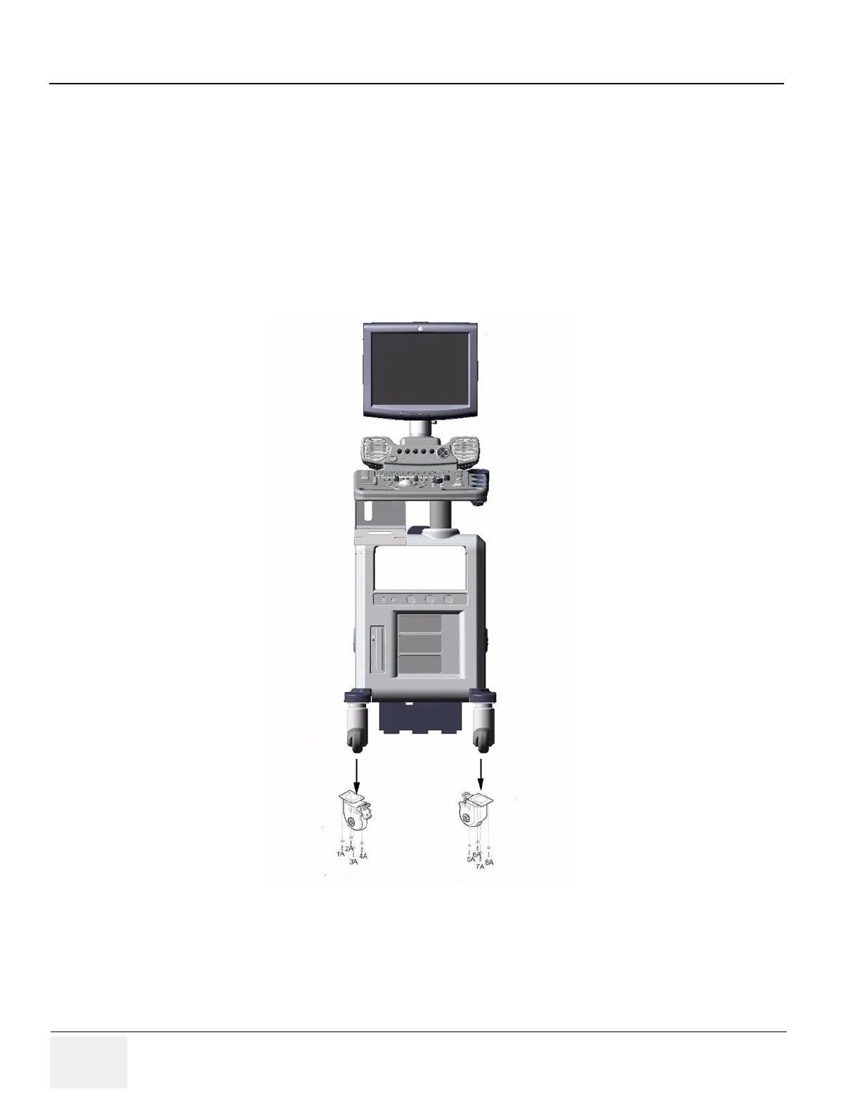
1.) This is the installation instruction of the Protect Cover. Refer to the figure below for the location of
the protect covers to be installed.
2.) Lift the system up front and fix it not to move during installation.
3.) Unscrew 8 screws (1A-8A) to remove the existing front casters. Refer to the figure below. keep the
screws for use.
4.) Replace them to Swivel Lock Casters by screwing 8 screws (1A-8A).
Figure 8-330 Swivel Lock Caster

Table of Contents

Other manuals for GE LOGIQ P5

Questions and Answers:

Question and Answer IconNeed help?

Do you have a question about the GE LOGIQ P5 and is the answer not in the manual?

GE LOGIQ P5 Specifications

General IconGeneral
Power Supply100-240VAC, 50/60Hz
Display15" LCD
Doppler ModesColor Doppler, Power Doppler
Imaging ModesB-Mode, M-Mode
ProbesConvex, Linear, Phased Array
ApplicationsAbdominal, Vascular, Cardiac, OB/GYN, Small Parts, Musculoskeletal
ConnectivityDICOM, USB, Ethernet
Probe Connectors3
PortabilityMobile
Operating Temperature10°C to 40°C
Relative Humidity30%

Related product manuals