GE HEALTHCARE
DIRECTION 5394141, REVISION 5 LOGIQ™ P5 SEVICE MANUAL
Section 8-2 - DISASSEMBLY/RE-ASSEMBLY 8-105
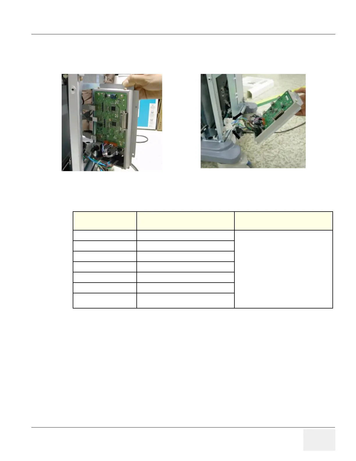
8-2-46-3 Removal procedure (cont’d)
5.) Disconnect three (3) USB connectors or 5 USB connectors from the rear panel and 2 AC power
connector. The 4D controller USB and ECG USB connector also connect to this rear panel PWA.
6.) Perform the following functional tests. If all are successful, include the debrief script provided below.
8-2-46-4 Mounting Procedure
Install the new parts in the reverse order of removal.
Figure 8-142 Open Rear Panel
Table 8-47 Functional Tests
Service Manual
Section
Functional Test / Diagnostic Test Debrief Script
Section 4-3-1
Power On/Boot Up
“Service Manual, Direction
5394141, Rev 1+, Section 8-2-46. Equipment
passed all required tests and is ready for use. “
Section 4-3-2
Power Off / Shutdown
Section 4-9-15
ARP Assy Function Validation Procedure
Section 4-5
Peripheral Checks
Section 10-5-2-2
Peripheral/Option Checks
Section 10-5-5
Physical Inspection
Section 10-6-3
Outlet Test - Wiring Arrangement - USA &
Canada

 Loading...


