GE HEALTHCARE
DIRECTION 5394141, REVISION 5 LOGIQ™ P5 SEVICE MANUAL
8-72 Section 8-2 - DISASSEMBLY/RE-ASSEMBLY
8-2-28-3 Removal procedure (cont’d)
7.) Unplug 3 connectors from the backplane and disconnect the 3P AC connector near bottom of the
backplane and disconnect the 2P connector near the nest cooling fan.
8.) Remove the Side Right Cover. Refer to the 8-2-16 "Side Right Cover" on page 8-52.
9.) Remove the EMI Cover R. Refer to the 8-2-27 "EMI Cover R" on page 8-69.
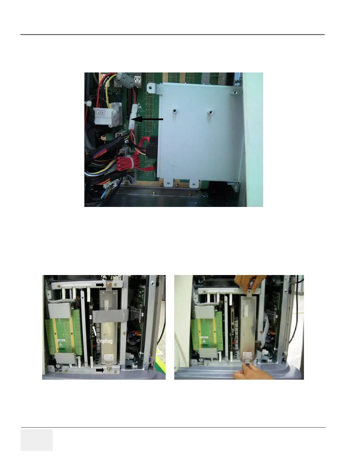
10.)Unplug the J14 connector and unscrew 2 screws (1-2). Pull out the APS/APS Pro assy carefully.
During take out the APS/APS Pro assy, the power connector on the backplane side should be
passed through the square hole on the backplane.
Figure 8-107 APS/APS Pro Connectors of backplane
Figure 8-108 Pull out the APS/APS Pro Assy
Cut the tie wrap
ODD Power Connector
ODD SATA Connector

 Loading...


