GE HEALTHCARE
DIRECTION 5394141, REVISION 5 LOGIQ™ P5 SEVICE MANUAL
5-6 Section 5-3 - Block Diagram
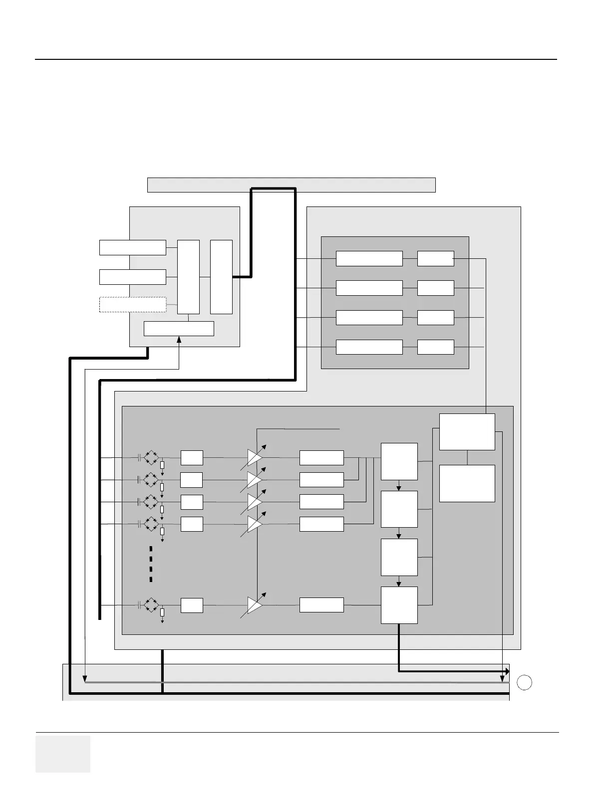
5-3-2 LOGIQ™ A5 Block Diagram
Differences between LOGIQ™ P5 and LOGIQ™ A5 are followings :
- CPU Module : LOGIQ™ P5 is Pentium M and LOGIQ™ A5 Celeron M
- Transmit pulse driver circuit : LOGIQ™ P5 is dual puse driver for CFM mode, but LOGIQ™
A5 is single pulse driver. So LOGIQ™ A5 circuit is more simple and cheap then LOGIQ™ P5.
- Keyboard : LOGIQ™ A5 keyboard doesn’t have CFM and PDI, CWD button.
Figure 5-5 LOGIQ™ A5 System Block Diagram
Probe Port #1
Probe Port #2
R
E
L
A
Y
M
U
X
RELAY Cont rol
P2RLY ASSY
R
R
R
R
R
ASIG connection
LNA
VCA
LNA
VCA
LNA
VCA
LNA
VCA
LNA
VCA
ADC 10bits
ADC 10bits
ADC 10bits
ADC 10bits
ADC 10bits
OQX2
OQX2
OQX2
OQX2
SDRAM
for
OQx2 & TPG2
TRBC
fpga
HV driver X 16 TPG2
HV driver X 16 TPG2
HV driver X 16 TPG2
HV driver X 16 TPG2
BTX ASSY
L1BFC ASSY
BL1TRX ASSY
PGC from SYSCONCM
ASIG ASSY
DC POWER from APS
FEBUS connected to SYSCONCM
RF Data to SYSCONCM
B
Probe Port #3
(Opt ion)
Probe Port #1
Probe Port #2
R
E
L
A
Y
M
U
X
RELAY Cont rol
P2RLY ASSY
R
R
R
R
R
ASIG connection
LNA
VCA
LNA
VCA
LNA
VCA
LNA
VCA
LNA
VCA
ADC 10bits
ADC 10bits
ADC 10bits
ADC 10bits
ADC 10bits
OQX2
Probe Port #1
Probe Port #2
R
E
L
A
Y
M
U
X
RELAY Cont rol
P2RLY ASSY
R
R
R
R
R
ASIG connection
LNA
VCA
LNA
VCA
LNA
VCA
LNA
VCA
LNA
VCA
ADC 10bits
ADC 10bits
ADC 10bits
ADC 10bits
ADC 10bits
OQX2
OQX2
OQX2
OQX2
SDRAM
for
OQx2 & TPG2
TRBC
fpga
HV driver X 16 TPG2
HV driver X 16 TPG2
HV driver X 16 TPG2
HV driver X 16 TPG2
BTX ASSY
L1BFC ASSY
BL1TRX ASSY
PGC from SYSCONCM
ASIG ASSY
DC POWER from APS
FEBUS connected to SYSCONCM
RF Data to SYSCONCM
B
OQX2
OQX2
OQX2
SDRAM
for
OQx2 & TPG2
TRBC
fpga
HV driver X 16 TPG2
HV driver X 16 TPG2
HV driver X 16 TPG2
HV driver X 16 TPG2
BTX ASSY
L1BFC ASSY
BL1TRX ASSY
PGC from SYSCONCM
ASIG ASSY
DC POWER from APS
FEBUS connected to SYSCONCM
RF Data to SYSCONCM
B
Probe Port #3
(Opt ion)

 Loading...


