GE HEALTHCARE
DIRECTION 5394141, REVISION 5 LOGIQ™ P5 SEVICE MANUAL
7-18 Section 7-5 - Common Diagnostics
7-5-4-2 CL1TRX/BL1TRX
These programs are provided for testing the CL1TRX /BL1TRZboard.
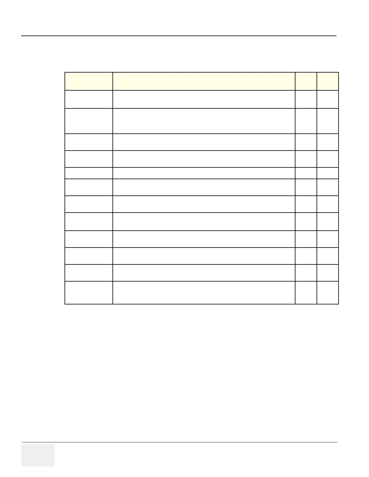
Table 7-3 FRU Test, CL1TRX/BL1TRX Diagnostics Menu
Menu
Descriptions
User
Level
Tools
Full Test
Performs all of the CL1TRX/BL1TRX board tests listed below
All None
Assy Revision
Test
Test EEPROM.
Send test pattern to write to EEPROM and read
Displays the board revision of the CL1TRX/BL1TRX board
All None
USC I/F Test
Checks if the DSP in SYSCONPM/SYSCONCM can access the CL1TRX/BL1TRX
boards via USB bus.
All None
FEBUS Test
Checks if the DSP in SYSCONPM/SYSCONCM can access the CL1TRX/BL1TRX
board via FE bus.
All None
HV Test
Read HV Power All None
PGC Test
Sends the test data High, Mid, Low level to PGC Register, then CL1TRX/BL1TRX
read result data and verify it.
All None
TEST Wave Test
Sends the test data High, Mid, Low level to Test wave Register, then CL1TRX/
BL1TRX read result data and verify it.
All None
TRX Data
Memory Test
Send the command to read / write to TRX data memory. All None
OQX2 Test
The DSP in L1SYSCON reads and writes the OQCARD registers in CL1TRX/BL1TRX
via FE bus.
All None
TPG2 Test
The DSP in L1SYSCON reads and writes the TPG2 registers in CL1TRX/BL1TRX via
FE bus.
RX Channel Test
Send test wave pattern to the input stage of preamp on CL1TRX/BL1TRX, perform 64
channel scanning, Read raw data, and analyze it.
TX Channel Test
Send test wave pattern to the CL1TRX/BL1TRX, read returned small signal, Read the
data and analyze it.
Note: APS/APS Pro HV test is required prior to the TRX TX channel test.

 Loading...


