EasyManuals Logo

GE LOGIQ P5 Service Manual

GE LOGIQ P5
532 pages
To Next Page IconTo Next Page
To Previous Page IconTo Previous Page
Page #278 background imageLoading...
Page #278 background image
GE HEALTHCARE
DIRECTION 5394141, REVISION 5 LOGIQ™ P5 SEVICE MANUAL
8-32 Section 8-2 - DISASSEMBLY/RE-ASSEMBLY
8-2-6-4 Assembly procedure (cont’d)
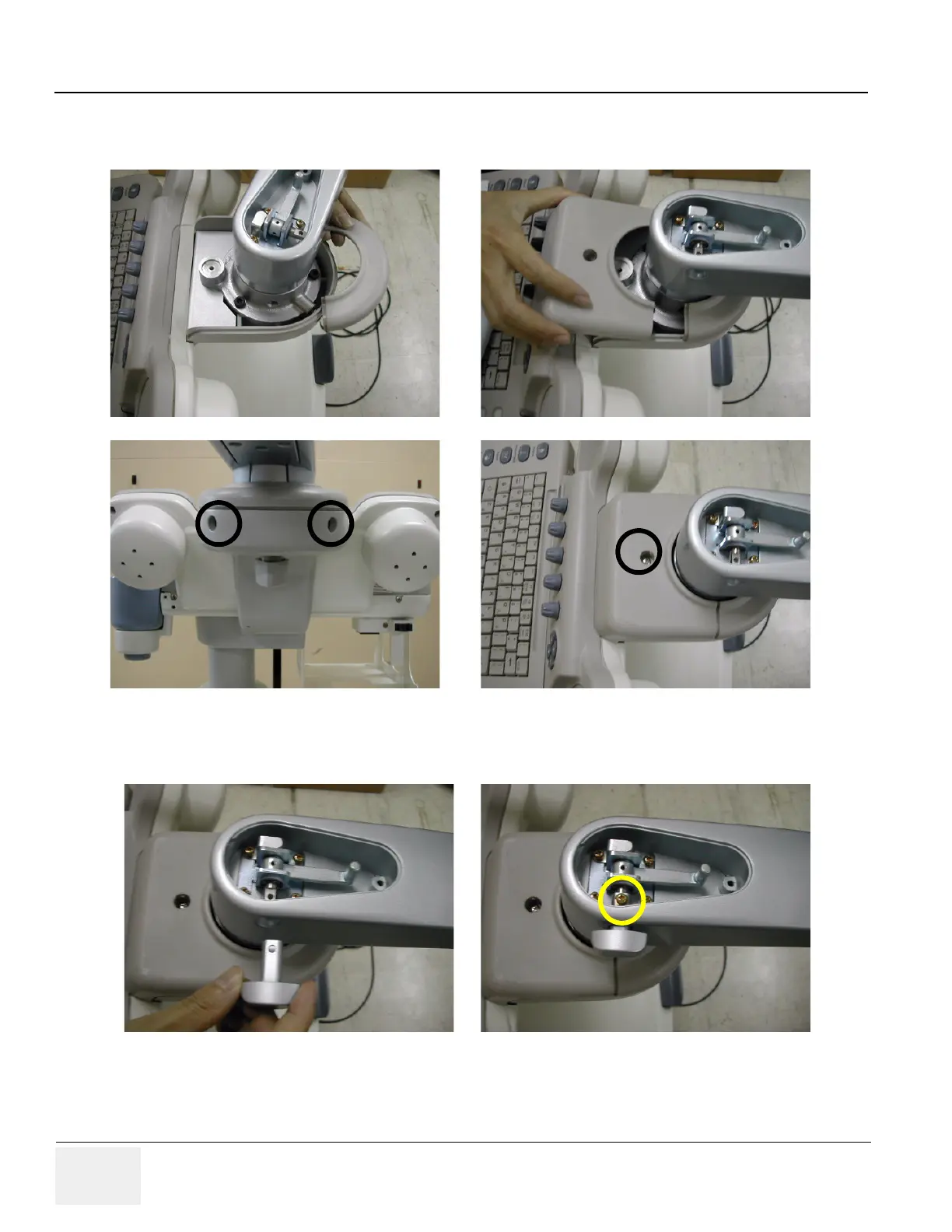
21.)Screw 3 screws (2159634, BH M4x10 WHT) after placing the neck front cover and neck Rear cover.
22.)Screw 1 screw (2159625, PH M4X8 W/SP) to assemble the Lock Knob.
Figure 8-58 Assembling the neck front cover and the neck rear cover
Figure 8-59 Assembling the Lock Knob

Table of Contents

Other manuals for GE LOGIQ P5

Questions and Answers:

Question and Answer IconNeed help?

Do you have a question about the GE LOGIQ P5 and is the answer not in the manual?

GE LOGIQ P5 Specifications

General IconGeneral
Power Supply100-240VAC, 50/60Hz
Display15" LCD
Doppler ModesColor Doppler, Power Doppler
Imaging ModesB-Mode, M-Mode
ProbesConvex, Linear, Phased Array
ApplicationsAbdominal, Vascular, Cardiac, OB/GYN, Small Parts, Musculoskeletal
ConnectivityDICOM, USB, Ethernet
Probe Connectors3
PortabilityMobile
Operating Temperature10°C to 40°C
Relative Humidity30%

Related product manuals