EasyManuals Logo

GE LOGIQ P5 Service Manual

GE LOGIQ P5
532 pages
To Next Page IconTo Next Page
To Previous Page IconTo Previous Page
Page #34 background imageLoading...
Page #34 background image
GE HEALTHCARE
DIRECTION 5394141, REVISION 5 LOGIQ™ P5 SEVICE MANUAL
1-6 Section 1-2 - Important Conventions
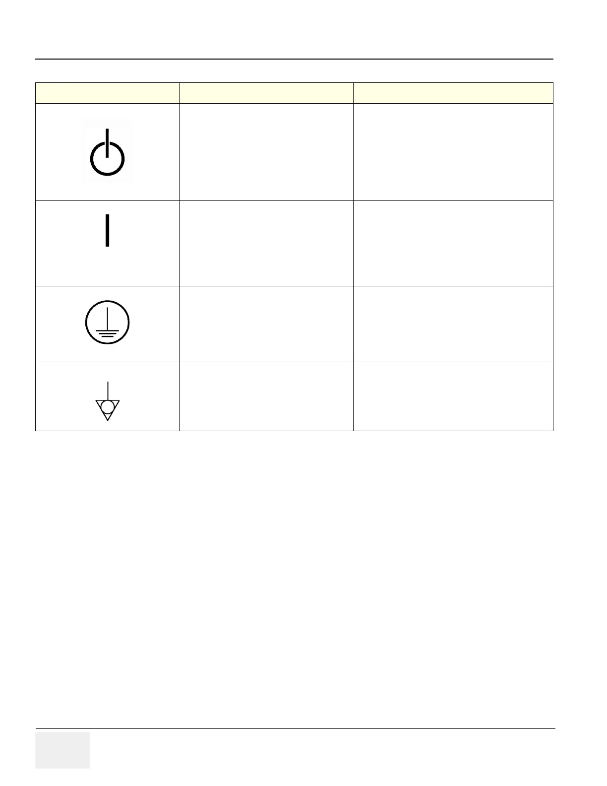
"OFF/Standby" Indicates the power off/
standby position of the power switch.
CAUTION
This Power Switch DOES NOT ISOLATE
Mains Supply
Adjacent to On-Off/Standby Switch
"Mains ON" Indicates the power on position of
the mains power switch.
"ON" Indicates the power on position of the
power switch.
CAUTION
This Power Switch DOES NOT ISOLATE
Mains Supply
Front Panel Switch
"Protective Earth" Indicates the protective
earth (grounding) terminal.
Internal
Indicates an earth GROUND potential
Product schematics
Peripherals
Table 1-5 Product Icons
LABEL/SYMBOL PURPOSE/MEANING LOCATION

Table of Contents

Other manuals for GE LOGIQ P5

Questions and Answers:

Question and Answer IconNeed help?

Do you have a question about the GE LOGIQ P5 and is the answer not in the manual?

GE LOGIQ P5 Specifications

General IconGeneral
Power Supply100-240VAC, 50/60Hz
Display15" LCD
Doppler ModesColor Doppler, Power Doppler
Imaging ModesB-Mode, M-Mode
ProbesConvex, Linear, Phased Array
ApplicationsAbdominal, Vascular, Cardiac, OB/GYN, Small Parts, Musculoskeletal
ConnectivityDICOM, USB, Ethernet
Probe Connectors3
PortabilityMobile
Operating Temperature10°C to 40°C
Relative Humidity30%

Related product manuals