EasyManuals Logo

GE LOGIQ P5 Service Manual

GE LOGIQ P5
532 pages
To Next Page IconTo Next Page
To Previous Page IconTo Previous Page
Page #435 background imageLoading...
Page #435 background image
GE HEALTHCARE
DIRECTION 5394141, REVISION 5 LOGIQ™ P5 SEVICE MANUAL
Section 8-7 - Mechanical Option Installation instruction 8-189
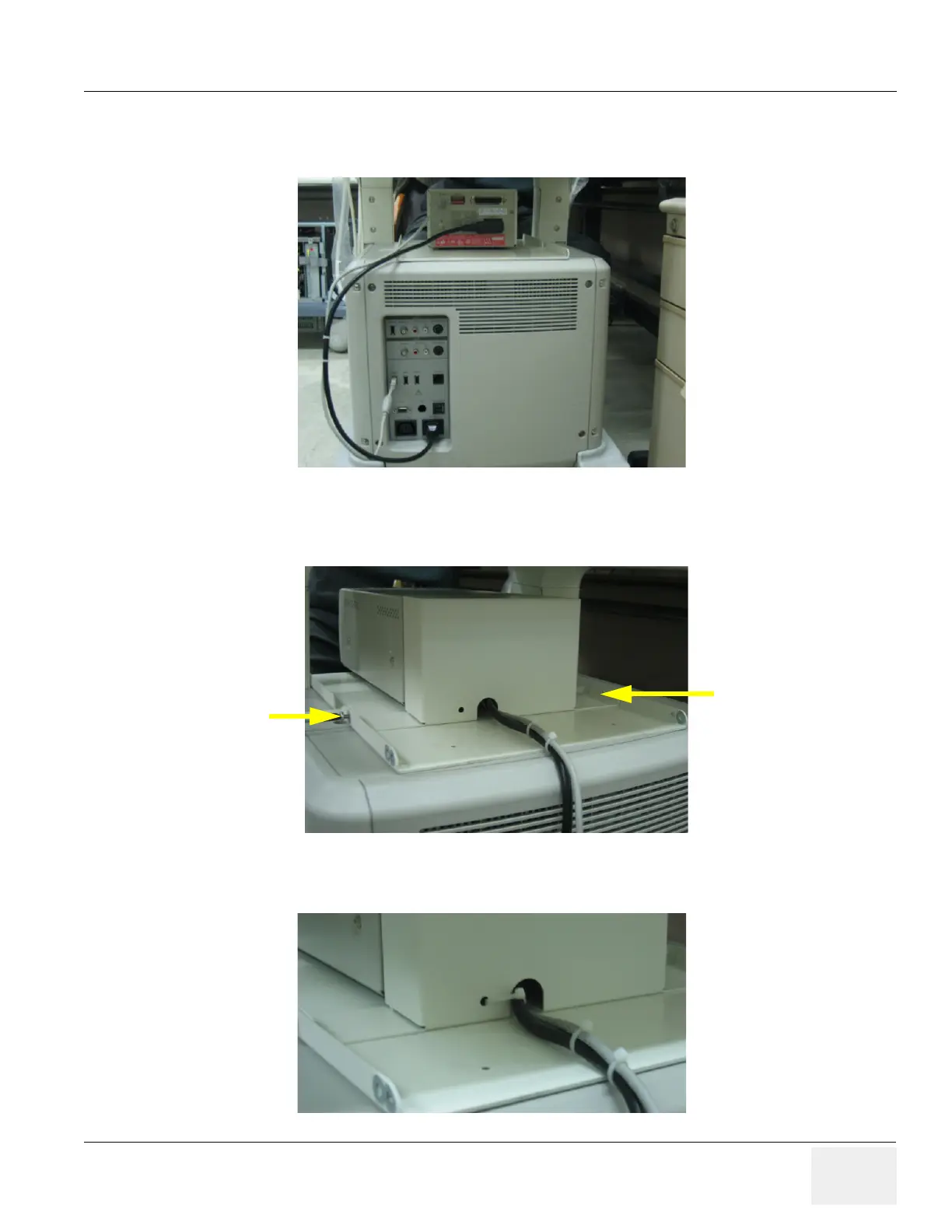
8-7-7 BW printer Fixture Middle installation (cont’d)
4.) Connect the USB cable and power cable from the printer to the system.
5.) Install BW hide bracket to the rear side of the BW printer and screw 2 screws(2159633, BH M4x8
WHT) to fix it.
6.) Tie the cables using the tie wrap as illustrated in the figure below.
Figure 8-266 BW Printer Fixture Middle installation
Figure 8-267 BW Printer Fixture Middle installation
Figure 8-268 BW Printer Fixture Middle installation

Table of Contents

Other manuals for GE LOGIQ P5

Questions and Answers:

Question and Answer IconNeed help?

Do you have a question about the GE LOGIQ P5 and is the answer not in the manual?

GE LOGIQ P5 Specifications

General IconGeneral
Power Supply100-240VAC, 50/60Hz
Display15" LCD
Doppler ModesColor Doppler, Power Doppler
Imaging ModesB-Mode, M-Mode
ProbesConvex, Linear, Phased Array
ApplicationsAbdominal, Vascular, Cardiac, OB/GYN, Small Parts, Musculoskeletal
ConnectivityDICOM, USB, Ethernet
Probe Connectors3
PortabilityMobile
Operating Temperature10°C to 40°C
Relative Humidity30%

Related product manuals