EasyManuals Logo

GE LOGIQ P5 Service Manual

GE LOGIQ P5
532 pages
To Next Page IconTo Next Page
To Previous Page IconTo Previous Page
Page #441 background imageLoading...
Page #441 background image
GE HEALTHCARE
DIRECTION 5394141, REVISION 5 LOGIQ™ P5 SEVICE MANUAL
Section 8-7 - Mechanical Option Installation instruction 8-195
8-7-10 Printer VCR DVD Fixture Top installation - UP23MD Printer (cont’d)
4.) Screw 4 screws(2159633, BH M4x8 WHT) on both sides to fix the color printer and DVD with top
bracket to the color printer top bracket.
5.) Connect the USB cable and Power cable from the color printer and DVD to the system. For more
wiring information, refer to the Basic Service Manual.
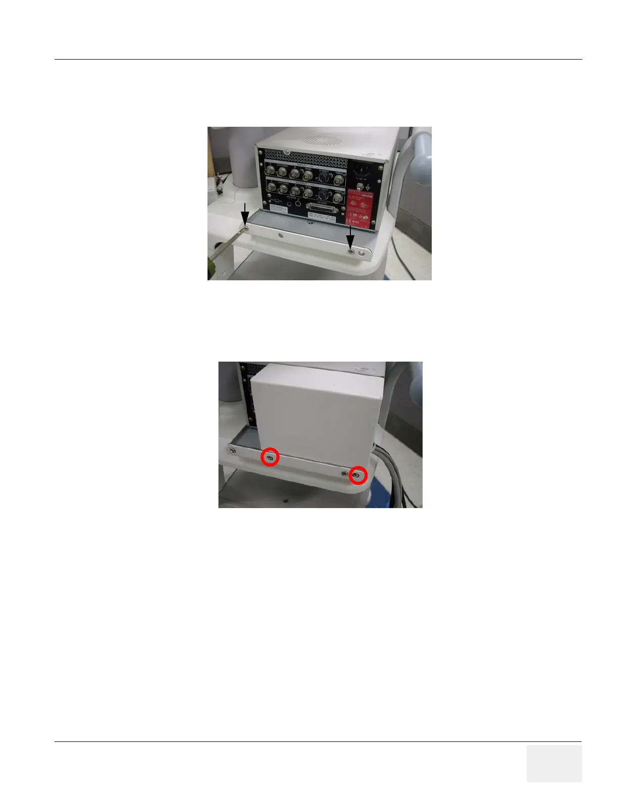
6.) Install hide bracket by screwing 2 screws(2159633, BH M4x8 WHT).
7.) Tie the cable properly using the tie wrap.
Figure 8-282 Printer VCR DVD Fixture installation top
Figure 8-283 Printer VCR DVD Fixture installation top

Table of Contents

Other manuals for GE LOGIQ P5

Questions and Answers:

Question and Answer IconNeed help?

Do you have a question about the GE LOGIQ P5 and is the answer not in the manual?

GE LOGIQ P5 Specifications

General IconGeneral
Power Supply100-240VAC, 50/60Hz
Display15" LCD
Doppler ModesColor Doppler, Power Doppler
Imaging ModesB-Mode, M-Mode
ProbesConvex, Linear, Phased Array
ApplicationsAbdominal, Vascular, Cardiac, OB/GYN, Small Parts, Musculoskeletal
ConnectivityDICOM, USB, Ethernet
Probe Connectors3
PortabilityMobile
Operating Temperature10°C to 40°C
Relative Humidity30%

Related product manuals