EasyManuals Logo

GE LOGIQ P5 Service Manual

GE LOGIQ P5
532 pages
To Next Page IconTo Next Page
To Previous Page IconTo Previous Page
Page #521 background imageLoading...
Page #521 background image
GE HEALTHCARE
DIRECTION 5394141, REVISION 5 LOGIQ™ P5 SEVICE MANUAL
Section 10-6 - Electrical Safety Tests 10-21
10-6-6-3Dale 600 Meter Procedure (cont’d)
5.) Set the meter's “FUNCTION” switch to LEAD TO GROUND position to measure the patient lead to
ground leakage current.
6.) Select and test each ECG lead positions (except ALL) of the LEAD selector, testing each to the
power condition combinations.
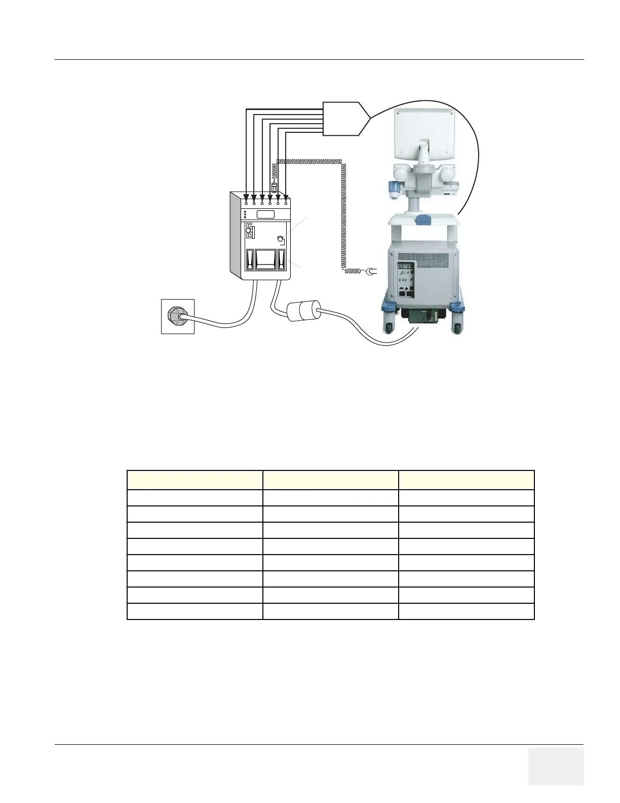
Figure 10-8 ECG Leakage Current Test
Table 10-19 Testing Power Conditions
ECG Power Meter’s Polarity Switch Meter’s Neutral Switch
ON NORM CLOSED
ON NORM OPEN
ON REVERSE CLOSED
ON REVERSE OPEN
OFF NORM CLOSED
OFF NORM OPEN
OFF REVERSE CLOSED
OFF REVERSE OPEN
ECG
Patient
Cable
ISO
Rocker
Switch
ECG
Lead
Selector

Table of Contents

Other manuals for GE LOGIQ P5

Questions and Answers:

Question and Answer IconNeed help?

Do you have a question about the GE LOGIQ P5 and is the answer not in the manual?

GE LOGIQ P5 Specifications

General IconGeneral
Power Supply100-240VAC, 50/60Hz
Display15" LCD
Doppler ModesColor Doppler, Power Doppler
Imaging ModesB-Mode, M-Mode
ProbesConvex, Linear, Phased Array
ApplicationsAbdominal, Vascular, Cardiac, OB/GYN, Small Parts, Musculoskeletal
ConnectivityDICOM, USB, Ethernet
Probe Connectors3
PortabilityMobile
Operating Temperature10°C to 40°C
Relative Humidity30%

Related product manuals