Patient Preparation
Electrode Placement
This section describes various methods for placing electrodes for resting ECGs on a
patient.
WARNING:
INACCURATE DIAGNOSIS - Improper connection of the leadwires to the electrodes
will cause inaccuracies in the ECG.
Make sure the leadwires are connected properly to the electrodes. Trace each
leadwire to its colored connector to make sure that it is matched to the correct
label leadwire connection location.
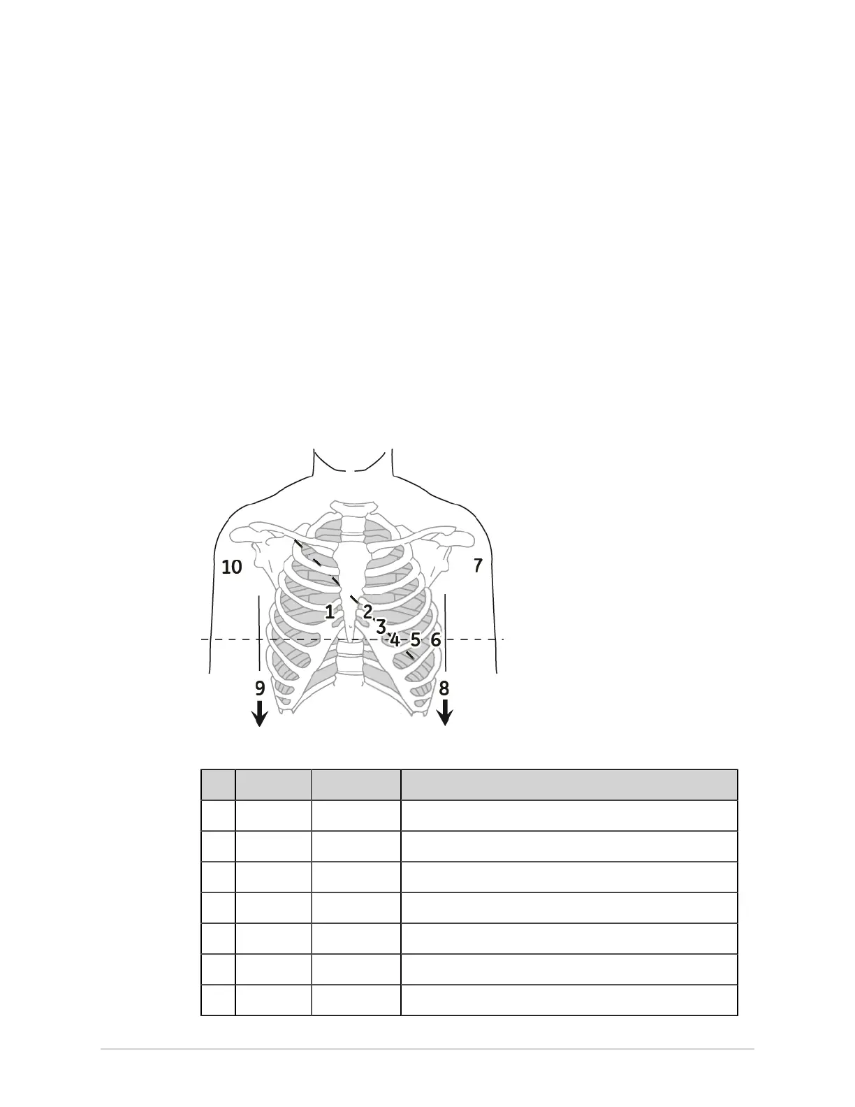
Standard 12–Lead Electrode Placement
To acquire a standard 12–lead ECG, use the electrode placement shown in the
diagram below.
Table 113: Standard 12–Lead Electrode Placement
Item AHA Label IEC Label Description
1 V1 red C1 red Fourth intercostal space at the right sternal border.
2 V2 yellow. C2 yellow Fourth intercostal space at the left sternal border.
3 V3 green. C3 green Midway between location 2 and 4.
4 V4 blue C4 brown Mid-clavicular line in the fifth intercostal space.
5 V5 orange C5 black Anterior axillary line on the same horizontal level as 4.
6 V6 violet C6 violet Mid-axillary line on the same horizontal level as 4 and 5.
7 LA black L yellow Left deltoid.
5864335-001-1 MAC
™
5 A4/MAC
™
5 A5/MAC
™
5 Lite 299