EasyManua.ls Logo

GW Instek PEL-2000A Series - Rear Panel Overview

GW Instek PEL-2000A Series
324 pages
To Next Page IconTo Next Page
To Previous Page IconTo Previous Page
Loading...
GETTING STARTED
29
Rear Panel Overview
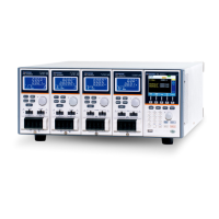
PEL-2004A
2
1
Go/NoGo
Output
GPIB
RS232C
USB-B
terminal
USB-A
terminal
Frame Control 1,2
Power switch,
Power Socket, Fuse
Channel
Control, 1~8
AWG 24
STRIP GAUGE
10.0 mm
1
CH CONT 1
1
CH CONT 2
1
CH CONT 3
1
CH CONT 4
1
CH CONT 5
1
CH CONT 6
1
CH CONT 7
1
CH CONT 8
SER. NO. LB
1
FRAME CONT
GO / NG OUTPUT
RS232C
Disconnect power cord
before replacing fuse.
T 3.15A 250V
REPLACE FUSE
AS SPECIFIED
AC
47 - 63 Hz
250 VA MAX.
100 - 120 VAC
200 - 240 VAC
Débranchez le cordon
d'alimentation avant de
remplacer le fusible.
GPIB
PEL-2002A
Power switch,
Power Socket, Fuse
Channel
Control, 1~4
Go/NoGo
Output
GPIB
RS232C
USB-B
terminal
USB-A
terminal
Frame Control 1,2
AC
RS232C
GO / NG OUTPUT
FRAME CONT
1
2
SER. NO. LB
CH CONT 4
1
CH CONT 3
1
CH CONT 2
1
CH CONT 1
1
10.0 mm
STRIP GAUGE
AWG 24
47 - 63 Hz
150 VA MAX.
100 - 120 VAC
200 - 240 VAC
T 3.15A 250V
REPLACE FUSE
AS SPECIFIED
Disconnect power cord
before replacing fuse.
Débranchez le cordon
d'alimentation avant de
remplacer le fusible.
GPIB
Go/NoGo
Output
GO / NG OUTPUT
The Go/NoGo Output terminal outputs a
pass (high)/fail (low) voltage for each
channel.
See page 289, 60 for details.

Table of Contents

Related product manuals