PEL-2000A Series User Manual
90
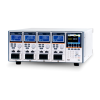
Channel Control
External channel control is used with the Channel
Control connectors. Each channel control
connector can activate each load, monitor voltage
and current and has an external voltage reference
input. The voltage and current monitors output
0~100% of the rated current/voltage as a voltage of
0~10V.
AWG 24
STRIP GAUGE
10.0 mm
1
CH CONT 1
1
CH CONT 2
1
CH CONT 3
1
CH CONT 4
1
CH CONT 5
1
CH CONT 6
1
CH CONT 7
1
CH CONT 8
SER. NO. LB
2
1
FRAME CONT
GO / NG OUTPUT
GPIB
RS232C
DISCONNECT POWER CORD
BEFORE REPLACING FUSE
AC input voltage range:
100-120Vac/ 200-240Vac
Frequency: 50/ 60Hz
Power rating: 250VA Max
250V
T 3.15A
REPLACE FUSE
FUSE RATING
AS SPECIFIED
WARNING
TO AVOID ELECTRIC SHOCK THE POWER CORD PROTECTIVE
DO NOT REMOVE COVERS. REFER SERVICING TO QUALIFIED PERSONNEL.
250V FUSE OF THE SPECIFIED TYPE AND RATING.
FOR CONTINUED FIRE PROTECTION. REPLACE FUSE ONLY WITH
NO OPERATOR SERVICEABLE COMPONENTS INSIDE.
GROUNDING CONDUCTOR MUST BE CONNECTED TO GROUND.
External Voltage
Reference
A voltage reference of 0-10V is used to represent 0-
100% of the rating voltage/current of a load
module. As seen below the external voltage
reference and the rating voltage/current have a
linear relationship. By varying the reference
voltage between 0~10V the voltage/current setting
will be changed accordingly.
External Voltage Control
Voltage/
Current
Setting
(Percent
Rating)
External Voltage
100%
0%
10V0V
 Loading...


