Measuring
Adapting to the transducer
MGCplus A0534-30.0 HBM: public 141
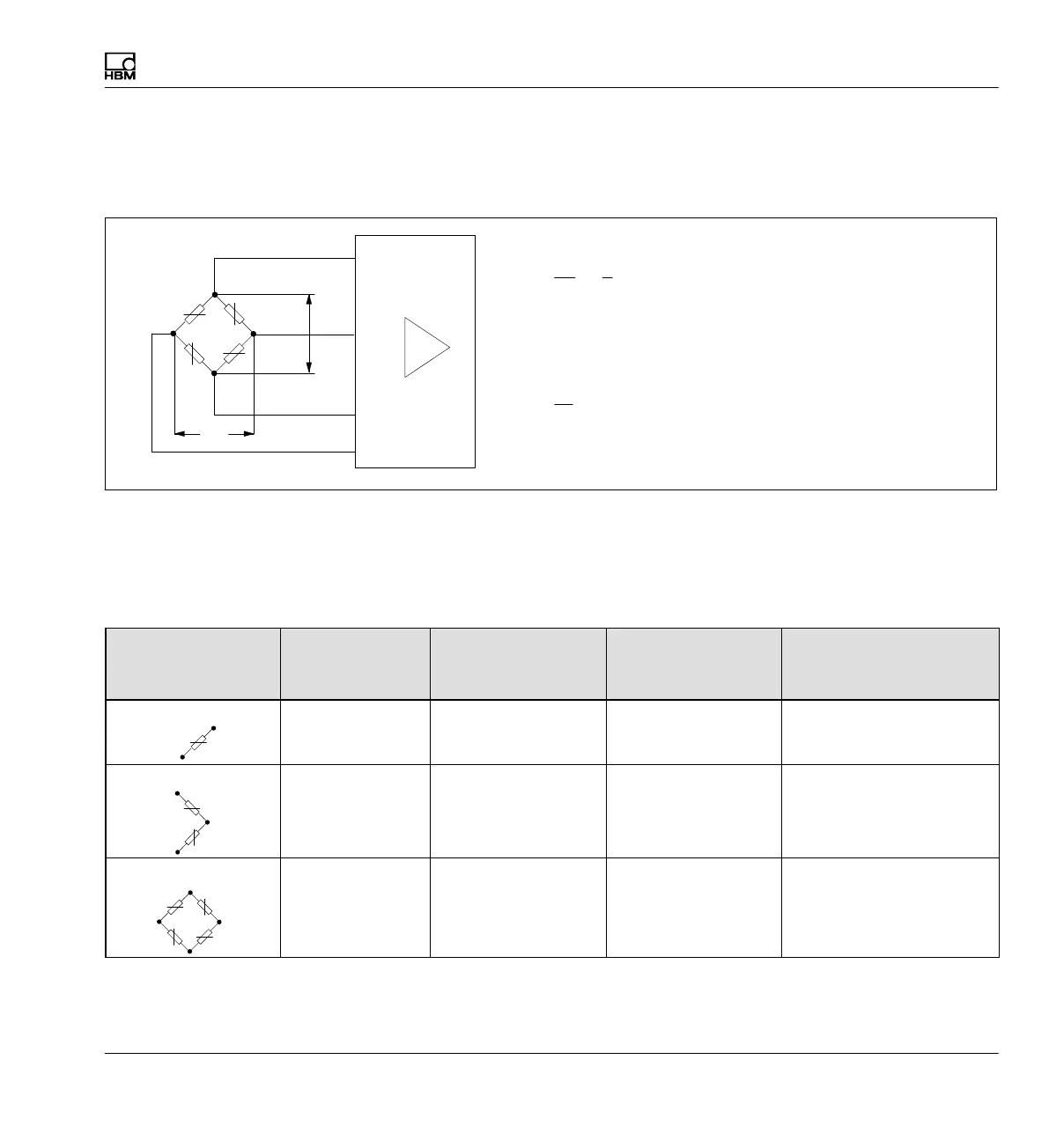
The resistance of the SG changes due to strain. Since this change lies in
the mΩ and μΩ range, a "Wheatstone bridge" must be used with great
accuracy.
1
2
3
4
U
A
U
B
ML10B
ML30B
ML55B
U
A
U
B
+
k
4
@
U
A
U
B
+ relativechangeoftheexcitationvoltage
=
Total strain
k = strain gage sensitivity (gage factor)
U
B
= Bridge excitation voltage
U
A
= bridge output voltage
Fig. 7.1 Wheatstone bridge
You can use the MGCplus measuring system to measure the strain of one
SG or the total strain of multiple SGs. The table below summarizes the pos
sible bridge circuits and the necessary device configuration:
Bridge type Number of
active strain
gages
Total strain Connection board Amplifier
e
Quarter
bridge
circuit
1 AP14 ML10B, ML30B,
ML55B
1)
e
1
Half bridge circuit
e
2
2 =
AP01i, AP03i,
AP14
ML10B, ML55B
1)
ML30B (only with AP14)
e
1
e
2
e
4
e
3
Full
bridge
circuit
4 =
AP01i, AP03i,
AP14
ML10B, ML30B,
ML55B
1)
, ML38B
2
)
1)
For the combination of ML55B with AP14, a one-time zero calibration must always be performed after setting up the measurement chain.
2)
Only in combination with AP01i and AP03i