Measuring
Adapting to the transducer
MGCplus A0534-30.0 HBM: public 149
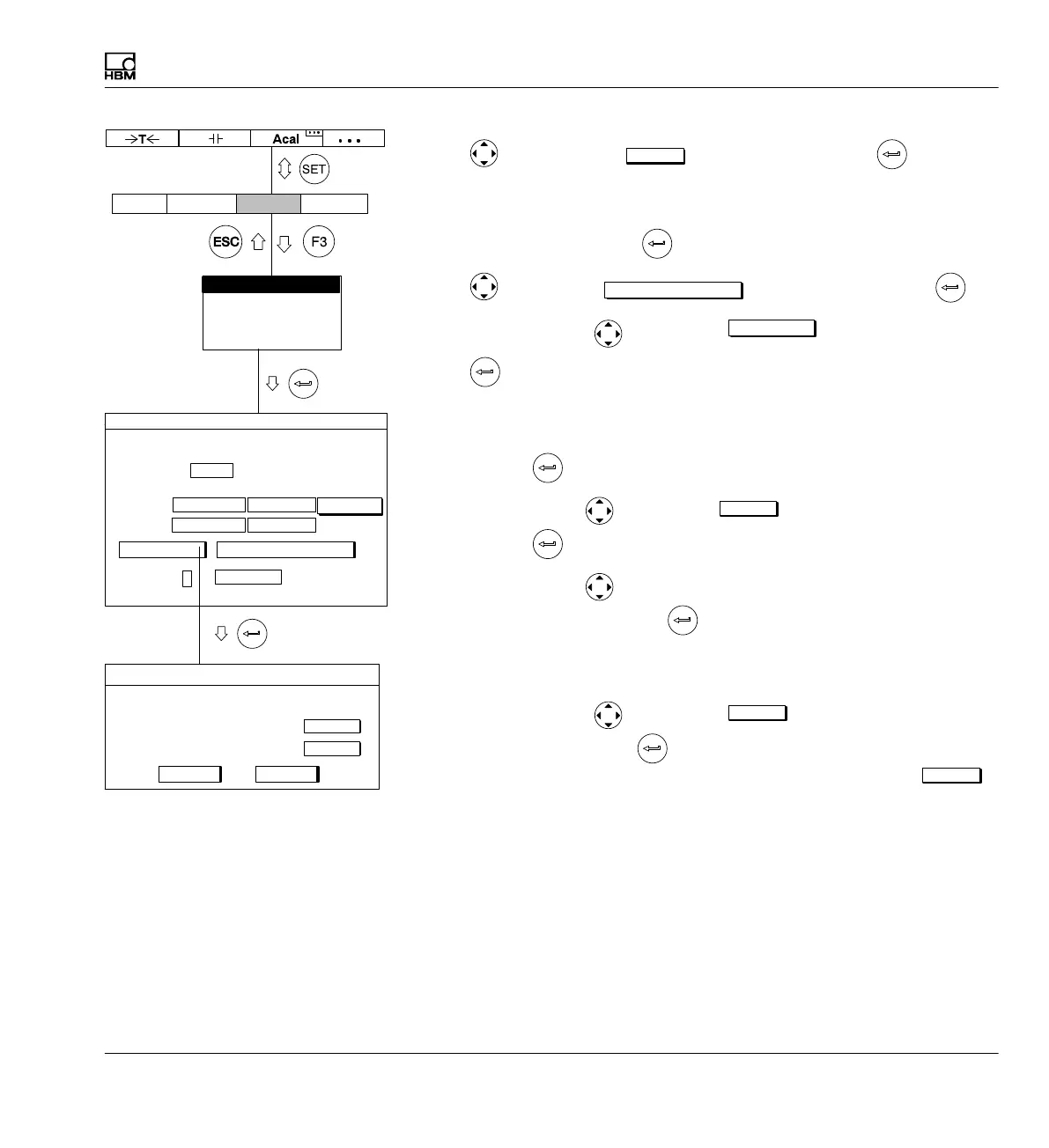
10. Use to switch to the
measure
button and confirm with (the mea
sured value appears in the right edit field of Zero point)
11. In the left edit field Nominal (rated) value enter the value 20 (under the
unit mm) and confirm with
.
12. Use
to select the
Adjust amplifier
button and confirm with .
13. Use the cursor keys
to select the
calibrate...
button and confirm
with
.
14. Move the transducer to the zero position.
15. In the left edit field for characteristic curve point 1 enter the value 0 and
confirm with
.
16. Use the cursor key
to select the
measure
button in line Point 1 and
confirm with
.
17. Use the cursor key
to select the left edit field in line Point 2, enter
the value 10 and confirm with
.
18. Position the gaging block under the probe tip of the displacement trans
ducer.
19. Use the cursor keys
to select the
measure
button symbol in line
Point 2. Now if you press
, a measurement starts and the current
measured value appears in mV/V on the left next to the button
measure
Type IND half bridge circuit
Current feed
Unit: mm mV/V
Zero pt.:
Nom. val.:
Gage factor:
mm
0.0000Point 1:
mV/V
0.0021
Shunt off
CancelOK
measure
10.000Point 2 5.0018
measure
Characteristic curve points
Unit
AmplifierSystem Display Options
Transducer
Signal conditioning
Display
Analog outputs
Switch
10.0000 ...
TRANSDUCER CHANNEL1
0.0000 ... 0.0000 ...
20.0000 ...
calibrate... Adjust amplifier
0.0000 ...
measure
2.5V