Additional functions
Limit value combination (single-channel modules only)
200 A0534-30.0 HBM: public MGCplus
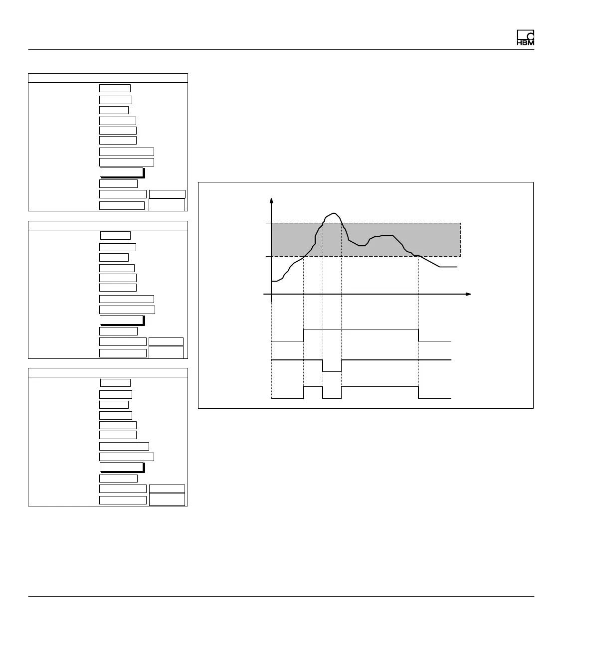
Example:
Task: The range between 10 kN and 20 kN will be monitored and assessed
as "OK". The assessment will be represented in the display by "OK" or
"NOK".
Solution: Limit switch 1 monitors the 10kN limit, limit switch 2 monitors the
20 kN limit. The two are combined together with "AND". The result of the
combination controls the output of limit switch 3.
kN
t
10
20
IO
0
1
LV1
0
1
LV2
0
1
LV3
1
1−LV1
Yes
10.000 ...
Gross
Limit switches
Name
Enable
Input signal
Level
Hysteresis
Direction
Output logic
0.010 ...
Exceed
Limit switch 1 Channel 1
Positive logic
Input
Message when On
Message when Off
Over 10kN...
Below 10kN...
Normal
Reverse
video
Free
kN
kN
Delay
define...
2...
1-LV2 ...
Yes
20.000...
Gross
Limit switches
Name
Enable
Input signal
Level
Hysteresis
Direction
Output logic
0.010 ...
Undershoot
Limit switch 2 Channel 1
Negative logic
Input
Message when On
Message when Off
Below 20kN ...
Over 20kN...
Normal
Reverse
video
Free
kN
kN
Delay
define...
3
1−LV3
Yes
0.000 ...
Gross
Limit switches
Name
Enable
Input signal
Level
Hysteresis
Direction
Output logic
0.010 ...
Exceed
Limit switch 3 Channel 1
Positive logic
Input
Message when On
Message when Off
IO
NOK
Normal
Reverse
video
Free
kN
kN
Delay
define...