164
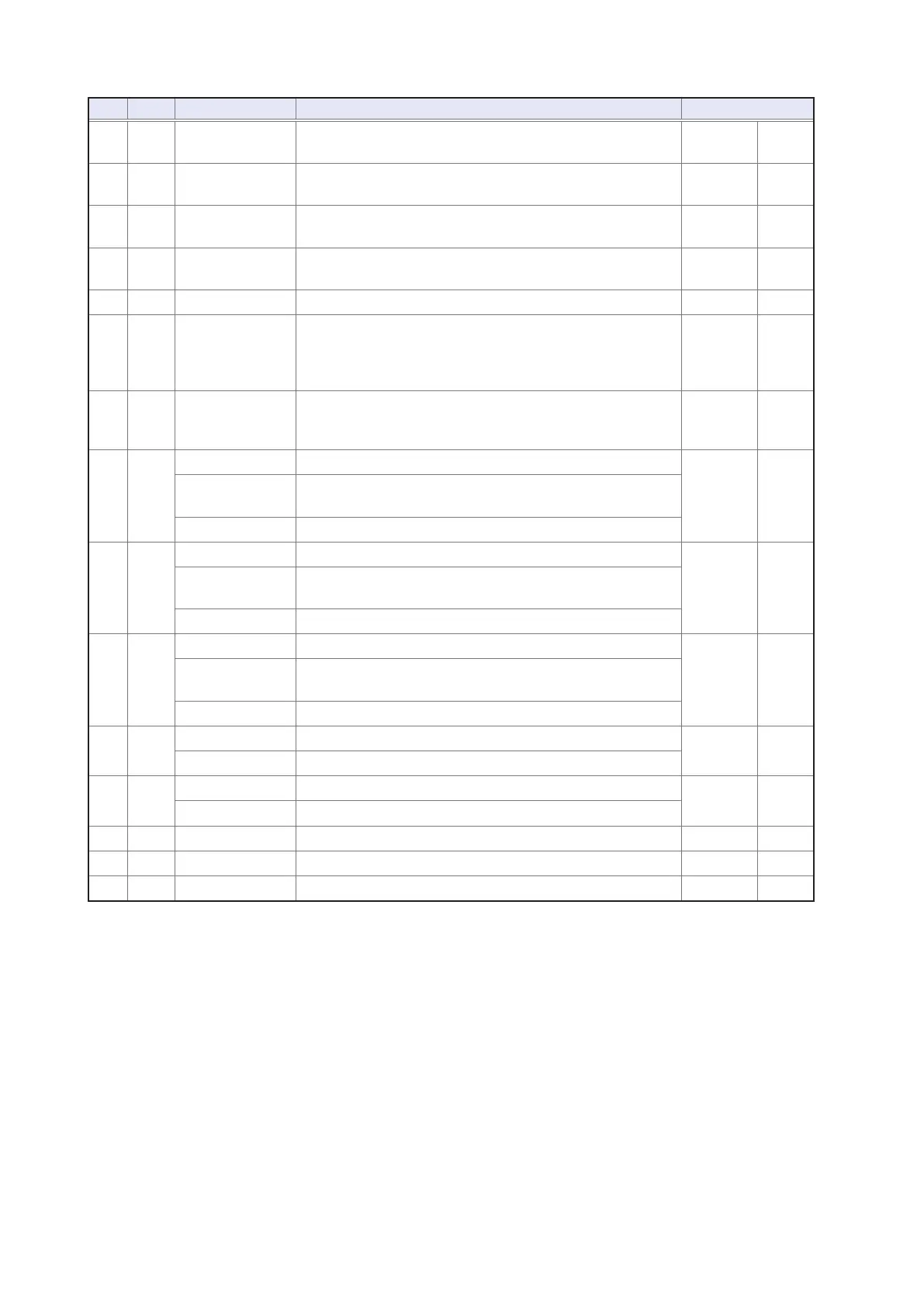
External Input/Output Connector and Signals
Pin I/O
*1
Signal name Function Logic
23 IN LD2
―――
Select panel number
(See "Input (IN) signal function details" (p. 167).)
Negative Level
24 IN LD4
―――
Select panel number
(See "Input (IN) signal function details" (p. 167).)
Negative Level
25 IN LD6
―――
Select panel number
(See "Input (IN) signal function details" (p. 167).)
Negative Level
26 IN LD_VALID
― ― ― ― ―――
Execute panel load
(See "Input (IN) signal function details" (p. 167).)
Negative Level
27 - ISO_COM Isolated common signal ground - -
28 OUT EOM
―――
This signal indicates that measurement is complete. “HI
(OFF)” indicates that measurement is in progress, while “LO
(ON)” indicates that measurement is complete. When LO
(ON), the comparator judgment results have been nalized.
Falling Edge
29 OUT INDEX
―― ― ――
Signal indicating that A/D conversion for the measurement
circuit has completed: When this signal changes from HI
(OFF) to LO (ON), the sample may be changed.
Falling Edge
30
*2
OUT BIN2
――― ―
Generates output when the BIN measurement result is BIN2.
Negative Level
PARA1-IN
―――――――
Generates output when the comparator judgment result is
IN for the No. 1 parameter.
D1-1
―― ―
BCD output signal
31
*2
OUT BIN4
――― ―
Generates output when the BIN measurement result is BIN4.
Negative Level
PARA3-HI
――――― ――
Generates output when the comparator judgment result is
HI for the No. 3 parameter.
D1-3
―― ―
BCD output signal
32
*2
OUT BIN6
――― ―
Generates output when the BIN measurement result is BIN6.
Negative Level
PARA3-LO
――――― ――
Generates output when the comparator judgment result is
LO for the No. 3 parameter.
D2-1
―― ―
BCD output signal
33 OUT BIN8
――― ―
Generates output when the BIN measurement result is BIN8.
Negative Level
D2-3
―― ―
BCD output signal
34 OUT BIN10
――― ――
Generates output when the BIN measurement result is BIN10.
Negative Level
D3-1
―― ―
BCD output signal
35 OUT D3-3
―― ―
BCD output signal Negative Level
36 OUT D4-1
―― ―
BCD output signal Negative Level
37 OUT D4-3
―― ―
BCD output signal Negative Level
*1: IN indicates signal input to the instrument, while OUT indicates signal output from the instrument.
*2: When BIN measurement is selected, refer to the top cell. When comparator measurement is selected, refer to the
middle cell. When BCD mode is selected, refer to the bottom cell.