Monitoring and Operating the Controller
222 UDC3500 Universal Digital Controller Product Manual 3/07
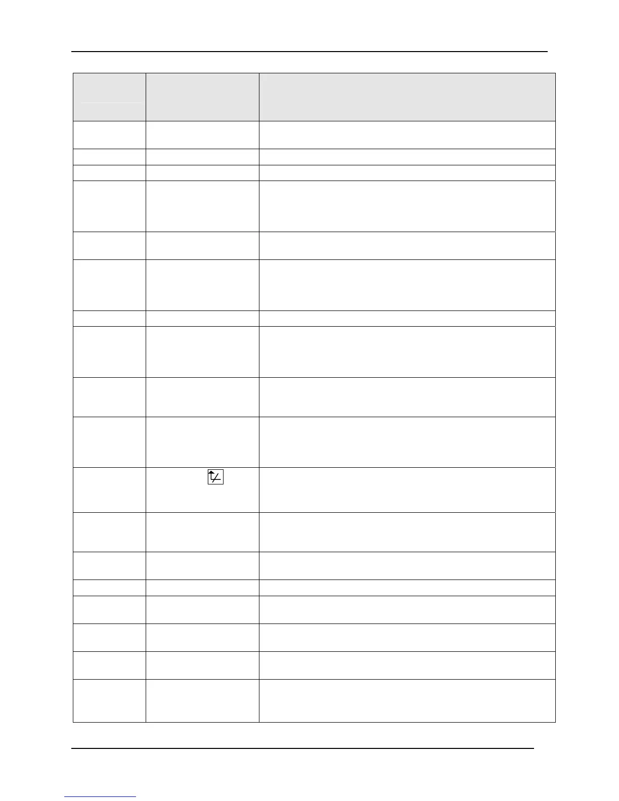
Digital Input
Selections
Display Indication Action on Contact Closure
Controller returns (toggles) to original state when contact
reopens unless otherwise noted
ToPID2 PIDSET 2 in lower
display
Selects PID set 2.
PV 2IN 2I (blinking)
Selects the PV to equal Input 2.
PV 3IN 3I (blinking)
Selects the PV to equal Input 3.
RERUN
Resets the Setpoint program back to the beginning of the first
segment in the program and leaves the program in the same
Run or Hold mode that it was in when the DI closed. Reopening
the contact has no effect.
TO RUN R in upper display
blinks
Starts a stopped SP Program. Reopening contact puts the
controller in Hold mode. This selection applies to either loop.
ToBEGIN
Resets the Setpoint Program back to the beginning of the first
segment in the program and places the program into the Hold
mode. Reopening the contact has no effect. This selection
applies to either loop.
STOP I
Disables PID Integral (I) action.
MAN FS MAN blinks
Unit goes to manual mode, output goes to the failsafe value.
This will cause a bump in the output when switching from
automatic to manual mode. The switch back from manual to
automatic mode is bumpless.
ToLOCK LOCKED on lower
display when a key is
pressed
Disables all keys.
ToAout
Output is forced to value set at control prompt “AUTO OUT”
when controller is in automatic mode. Reopening contact
returns the controller to the normal output. This selection is only
available on Loop 1.
TIMER
Timer clock (
) and
time appear in lower
display.
Starts timer (momentary operation). Reopening switch has no
effect.
AM STA
Causes switch to Auto Manual Station mode. Refer to Figure
4-2 in Section 4.16 for auto manual station information. This
selection is only available on Loop 1.
ToTUNE TUNE ON in lower
display
Starts the Accutune process. Opening the switch has no effect.
SPinit
Forces the SP to initialize at the current PV value.
TRACK1 O in upper display
blinks
Allows Output 1 to track Input 2.
TRACK2 O in upper display
blinks
Allows Output 2 to track Input 2.
ToOUT2 O in upper display
blinks
Allows Output 2 to override Output 1.
TO RSP SP annunciator blinks
Lower display shows
RSP
Puts the controller into Remote Setpoint. When contact opens,
the controller returns to former operation, local or remote
setpoint.

 Loading...


