Installation
3/07 UDC3500 Universal Digital Controller Product Manual 27
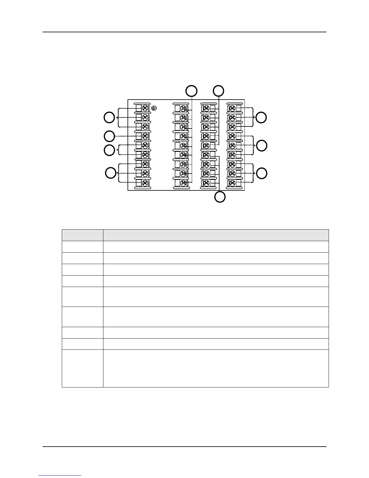
Wiring the Controller
Using the information contained in the model number, select the appropriate wiring
diagrams from the composite wiring diagram below. Refer to the individual diagrams
listed to wire the controller according to your requirements.
See table for callout details
4
5
6
7
8
9
10
11
12
13
14
15
16
17
L1
L2/N
22
23
24
25
26
27
18
19
20
21
31
32
33
34
35
36
28
29
30
6
5
4
1
2
3
7
8
9
9
Figure 2-4 Composite Wiring Diagram
Callout Details
1 AC/DC Line Voltage Terminals. See Figure 2-5.
2 First Current Output Terminals. See Figure 2-12.
3 Output 2 Option Terminals. See Figure 2-14 through Figure 2-19.
4 Input #1 Terminals. See Figure 2-6.
5 Input #2 Terminals. See Figure 2-7.
Dual HLAI Inputs #2 and #4 Terminals. See Figure 2-9 and Figure 2-11.
6 Input #3 Terminals. See Figure 2-8.
Dual HLAI Inputs #3 and #5 Terminals. See Figure 2-10 and Figure 2-11.
7 Digital Inputs Terminals. See Figure 2-23.
8 Optional Relays Terminals (Relays 3, 4 and 5). See Figure 2-24.
9 Optional Interface
Second Current Output Terminals. See Figure 2-13.
RS-485 Communications Terminals. See Figure 2-20.
Ethernet Communications Terminals. See Figure 2-22.

 Loading...


