Modbus Read, Write and Override Parameters plus Exception Codes
426 UDC3500 Universal Digital Controller Product Manual 3/07
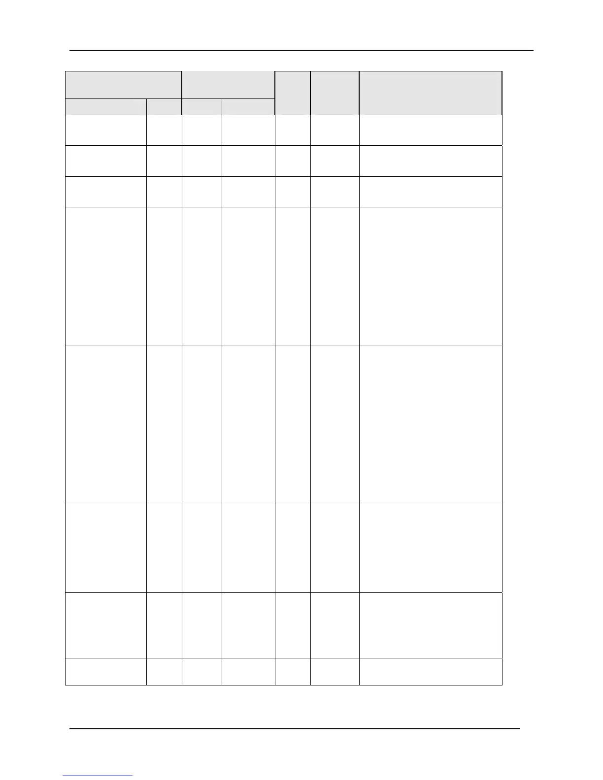
Parameter
Register
Address
Data
Type
Access Data Range or
Enumerated Selection
Description ID Hex Decimal
Alarm 2
Latching
228 00E4 228 INT R/W
0 = Non Latching
1 = Latching
Alarm 3
Latching
229 00E5 229 INT R/W
0 = Non Latching
1 = Latching
Alarm 4
Latching
230 00E6 230 INT R/W
0 = Non Latching
1 = Latching
Alarm 1 and 2
States (Read
Only)
201 00C9 201 INT R
State = 0 = Not in Alarm
State = 1 = In Alarm
Bit 0 = Alarm 1 SP1 State
Bit 1 = Alarm 1 SP2 State
Bit 2 = Alarm 2 SP1 State
Bit 3 = Alarm 2 SP2 State
Event = 0 = Low
Event = 1 = High
Bit 4 = Alarm 1 SP1 Event
Bit 5 = Alarm 1 SP2 Event
Bit 6 = Alarm 2 SP1 Event
Bit 7 = Alarm 2 SP2 Event
Alarm 3 and 4
States (Read
Only)
248 00F8 248 INT R
Event = 0 = Low
Event = 1 = High
Bit 0 = Alarm 3 SP1 Event
Bit 1 = Alarm 3 SP2 Event
Bit 2 = Alarm 4 SP1 Event
Bit 3 = Alarm 4 SP2 Event
State = 0 = Not in Alarm
State = 1 = In Alarm
Bit 4 = Alarm 3 SP1 State
Bit 5 = Alarm 3 SP2 State
Bit 6 = Alarm 4 SP1 State
Bit 7 = Alarm 4 SP2 State
Alarm Blocking 202 00CA 202 INT R/W
0 = Disable
1 = Block Alarm 1
2 = Block Alarm 2
3 = Block Alarm 3
4 = Block Alarm 4
5 = Block Alarms 1 and 2
6 = Block Alarms 1,2,3
7 = Block Alarms 1,2,3,4
Diagnostic
Alarm
154 009A 154 INT R/W
0 = Disable
1 = Alarm 1
2 = Alarm 2
3 = Alarm 3
4 = Alarm 4
5 = DISWARN
Alarm Message 239 00EF 239 INT R/W
0 = Disable
1 = Enable

 Loading...


