Installation
3/07 UDC3500 Universal Digital Controller Product Manual 29
22
23
24
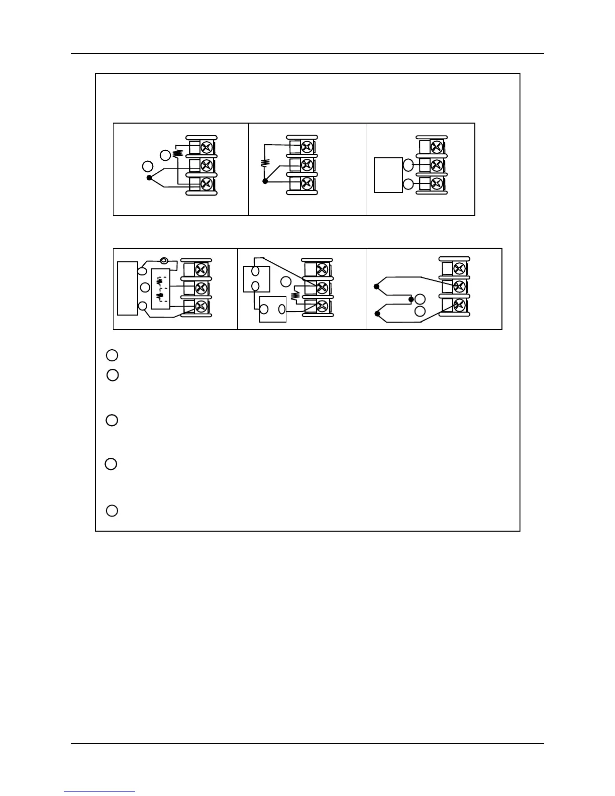
Use Thermocouple
extension wire only
Thermocouple
RTD
Milliamps
–
+
+
R
–
1
2
3
–
Volt
source
+
100K
100K
Power
Supply
–+
Xmitter
+
–
250
22
23
24
+
R
–
22
23
24
+
R
–
1
22
23
24
+
R
–
1
Input #2
mV or
Volt
source
22
23
24
Use Thermocouple
extension wire only
+
R
–
Thermocouple Differential
+
+
–
–
2
3
22
23
24
+
R
–
34
35
36
Use Thermocouple
extension wire only
Thermocouple
RTD
Milliamps
–
+
+
R
–
1
2
3
–
Volt
source
+
100K
100K
Power
Supply
–+
Xmitter
+
–
250
34
35
36
+
R
–
34
35
36
+
R
–
3
34
35
36
+
R
–
3
Input #1
mV or
Volt
source
34
35
36
Use Thermocouple
extension wire only
+
R
–
Thermocouple Differential
+
+
–
–
4
1
34
35
36
+
R
–
3
4
1
The millivolt values for the Thermocouple Differential Input are for a pair of J thermocouples at an ambient
temperature mean of 450°F / 232°C. Cold Junction Compensation is not required for this input type.
5
2
5
3
2
This controller does not produce a steady current for burnout detection. For that reason, when a
thermocouple is used in parallel with another instrument, it may be desirable to configure the burnout
selection for this controller to “NOFS” and use the burnout current from the other instrument to also drive
this controller. The Failsafe Output must be set to ensure proper operation when the thermocouple fails.
Splice and tape this junction between the two thermocouples. This junction may be located anywhere
between the thermocouples and the instrument terminals, it does not need to be close to the other
thermocouple junctions. Both thermocouples must be of the same type. For the highest accuracy, the
thermocouples should be matched or, preferably, made from the same batch of wire.
Remove the “R” terminal screw and install the C/J Sensor in its place. Connect the tang to the “
−
“ terminal.
The 250 ohm resistor for milliamp inputs or the voltage divider for 0 to10 Volt or –1 to 1Volt inputs are
supplied with the controller when those inputs are specified. These items must be installed prior to start up
when the controller is wired. For 0-20 mA, -1 to 1 Volt and 0-10 Volt applications, the resistor should be
located at the transmitter terminals if Burnout detection is desired.
Carbon, Oxygen, Millivolt or Volts
except 0 to 10 Volts or –1 to 1 Volts
0-10 Volts or –1 to 1 Volts
Figure 2-6 Input 1 Connections

 Loading...


