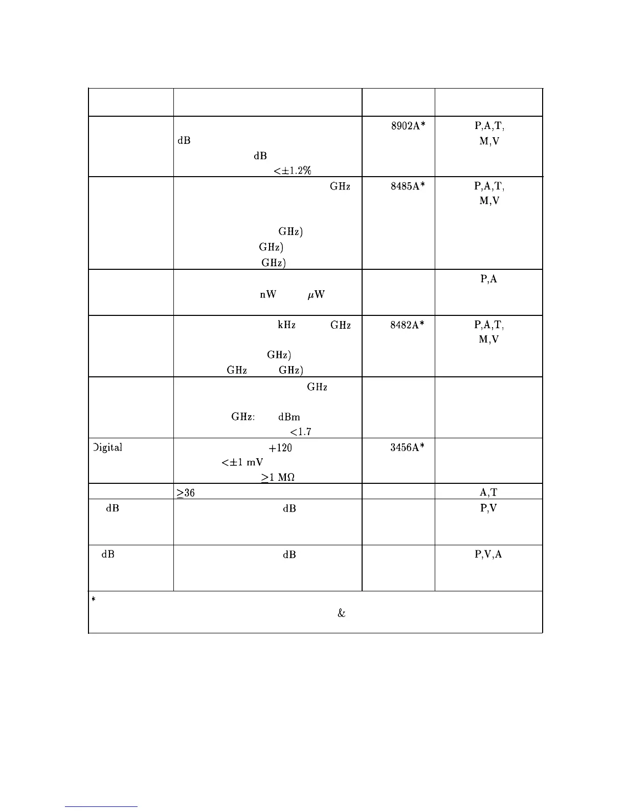
Table 1-4. Recommended Test Equipment (continued)
Instrument
Critical Specifications
Recommended Use
for Equipment Substitution Model
Measuring
Compatible w/Power Sensors
HP
8902A*
PAT,
Receiver
dB Relative Mode
M,V
Resolution: 0.01 dB
Reference Accuracy: <&1.2%
Power Sensor
Frequency Range: 50 MHz to 6.9 GHz
HP
8485A*
PAT,
Maximum SWR:
M,V
1.15 (50 to 100 MHz)
1.10 (100 MHz to 2 GHz)
1.15 (2.0 to 6.5 GHz)
1.20 (12.4 to 18 GHz)
Power Sensor
Frequency Range: 250 MHz to 350 MHz
HP 8484A
P,A
Power Range: 100
nW
to 10
PW
Maximum SWR: 1.15 (250 to 350 MHz)
Power Sensor
Frequency Range: 100 kHz to 2.9 GHz HP 8482A*
PAT,
Maximum SWR:
M,V
1.1 (1 MHz to 2.0 GHz)
1.30 (2.0 GHz to 2.9 GHz)
4mplifier
Frequency Range: 2.0 to 2.9 GHz HP 11975
P
Minimum Output Power (Leveled)
2.0 to 8.0 GHz: $16
dBm
Output SWR (Leveled):
<1.7
Digital Voltmeter Range: -15 V dc to +120 V dc
Accuracy:
<fl
mV on 10 V Range
Input Impedance:
21
Ma
DVM Test Leads
236
inches, alligator clips, probe tips
10 dB Step Attenuation Range: 30 dB
Attenuator Frequency Range: dc to 80 MHz
Connectors: BNC (f)
1 dB Fixed Attenuation Range: 12 dB
Attenuator
Frequency Range: dc to 80 MHz
Connectors: BNC (f)
’
Part of Microwave Workstation
HP
3456A*
A
HP 34118A
A,T
HP 355D
p,v
HP 355C
P,V,A
P = Performance Tests; A = Adjustments; M = Test
&
Adjustment Module; T = Troubleshooting
V = Operation Verification
1-14 General Information