33.If the voltage monitored in step 23 is correct with a 0
dBm
output but not with -15
dBm
output, suspect A14U201 or A14U202. If the voltage does not change, check the YTO
PLL Loop’s divide-by-two circuits as follows:
Set the signal generator for an 80 MHz output.
Measure
A14U203 pin 2 with an active probe and a spectrum analyzer. The signal
should be approximately 0
dBm
(ECL levels) and 47.35 MHz (94.7 MHz Main Roller
Frequency divided by two).
The signal at A14U205 pin 2 should measure 40 MHz at approximately 0
dBm.
Note
A14U205 is turned off during YTO FM coil sweeps (LO spans between 1.01
and 20 MHz).
34. Place jumper A14J23 in the NORMAL position and connect W32 to
A14J501.
35. Steps 27 through 31 verify that the YTO-loop error voltage is reaching the FM coil. Refer
to function blocks N and 0 of Al4 Frequency Control Schematic (sheet 2 of 5) in the
Component-Level Information binder. To troubleshoot the YTO FM Coil Driver, refer to
step 6 of “First LO Span Problems (1 MHz to 20 MHz).”
36. Remove jumper
A14J23 and connect a dc power supply to A14J23 pin 2. Set the dc
power supply to
t7.5
Vdc.
37. Verify the nominal test-point voltages listed in Table 10-13.
38. Change the input voltage to -7.5 volts and re-verify that the voltages listed in
Table
lo-13
are the same except for a change in polarity.
39. The Main-Loop Error-Voltage Driver has a gain of either 1.5 or 15; the analyzer’s
firmware controls the gain during the locking process. The error voltage is read by the
ADC on the A3 Interface assembly.
U324D
calibrates out any offsets from true ground.
A14U326A inverts the sense of the YTO loop to lock the YTO on lower sampler-sidebands
(YTO frequency
<
(sampler frequency xsampler harmonic)). The Main Roller frequency
indicated in the FREQ DIAGNOSE menu will be negative in this situation. Changing the
CENTER FREQ to 678.8 MHz with a SPAN of 0 Hz will change the switch setting of U326A
and invert the voltages listed in Table 10-13.
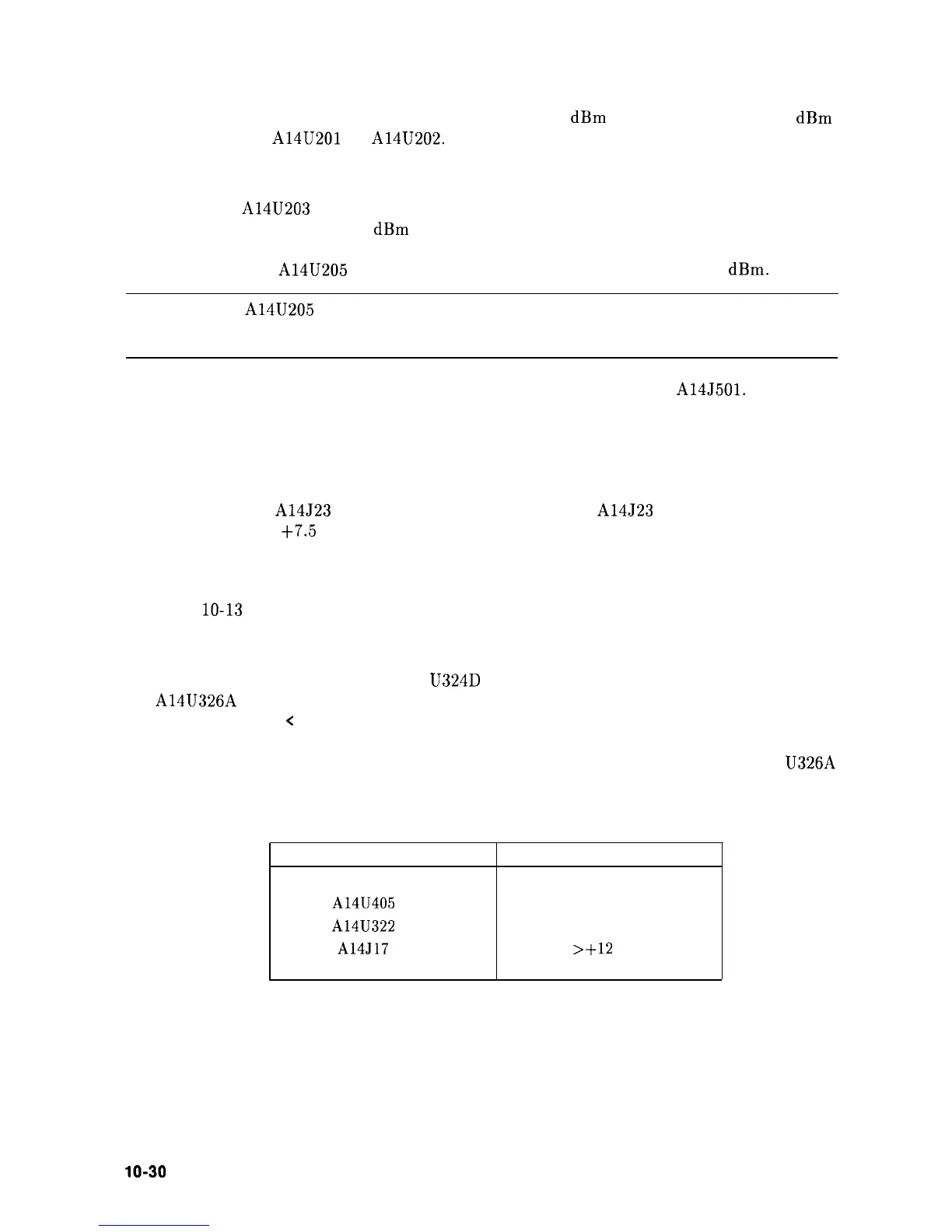
Table 10-13. Voltages in FM Coil and Main Loop Drivers
Measurement Points
Voltages
A14U405
pin 6
+2.8 Vdc
A14U322
pin 2
0 Vdc
A14J17
pin 4
>+12
Vdc
40. Place jumper A14J23 in the TEST position.
lo-30
Synthesizer Section