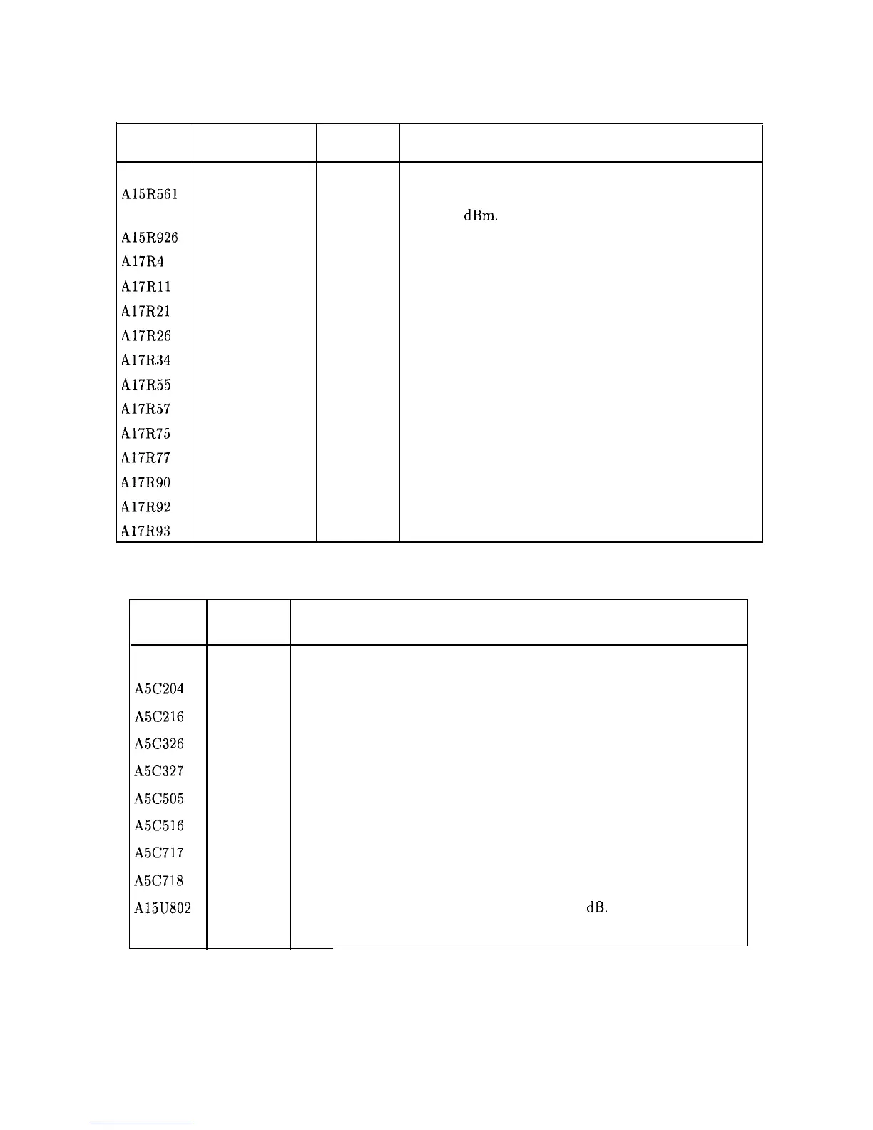
Table 2-2. Adjustable Components (3 of 3)
Reference
Adjustment Adjustment Description
Designator
Name
Number
A15R561
CAL AMPTD
11
Adjusts amplitude of the 300 MHz calibrator signal
to -10.0
dBm.
A15R926 EXT BIAS ZERO
14
Adjusts zero bias point of external mixer bias.
A17R4 Z GAIN
2
Adjusts maximum intensity.
A17Rll
CUTOFF
2
Adjusts intensity to turn off blanked lines.
A17R21
Z FOCUS
2
Adjusts focus for lines of different brightness.
A17R26
X FOCUS
2
Adjusts focus at the left and right corners of the display
A17R34
COARSE FOCUS
2
Adjusts focus at the center of the display.
A17R55
X GAIN
2
Adjusts the horizontal-deflection amplifier gain.
A17R57
X POSN
2
Adjusts the CRT horizontal position.
Al7R75
Y GAIN
2
Adjusts the vertical-deflection amplifier gain.
A17R77
Y POSN
2
Adjusts the CRT vertical position.
A17R90
TRACE ALIGN
2
Adjusts the display axis rotation.
A17R92
DDD
2
Adjusts focus of the center of the display.
417R93
ASTIG
2
Adjusts for the spot roundness on the CRT display.
Table 2-3. Factory Selected Components
Reference Adjustment
Designator Number
A5C204
A5C216
A5C326
A5C327
A5C505
A5C516
A5C717
A5C718
A15U802
Basis of Selection
3
Selected to optimize center frequency of LC tank that loads the crystal.
3
Selected to optimize center frequency of LC tank that loads the crystal.
3
Selected to optimize LC pole center frequency.
3
Selected to, optimize LC pole center frequency.
3
Selected to optimize center frequency of LC tank that loads the crystal.
3
Selected to optimize center frequency of LC tank that loads the crystal.
3
Selected to optimize LC pole center frequency.
3
Selected to optimize LC pole center frequency.
16
Selected to set the gain of the second IF to 12 dB.
2-6 Adjustment Procedures