BNC CABLE
FREQUENCY COUNTER
S&Wⅈ
I
2
ED
I
FREOUENCY
STANDARD
EXT
SMA CABLE
TEST CABLE
A
I
5’J
1
0
1
AdA
Jl
SK1102
Figure 10-2. Sampler and Sampling Oscillator Test Setup
24. At each combination, the frequency counter should measure a sampler IF of 100.2 MHz
&500
Hz. (The Offset PLL’s sampling oscillator tunes to the frequencies listed in the
table.) If the frequency counter does not read a sampler IF of 100.2 MHz, suspect the Al5
RF Assembly.
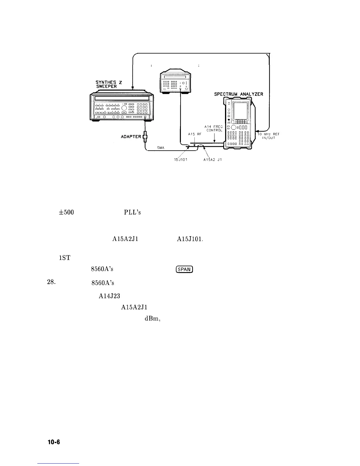
25. Reconnect W34 to
A15A2Jl
and W32 to
A15JlOl.
26. If YTO unlocks only with certain center frequency and span combinations, terminate the
1ST
LO OUTPUT in 50 ohms.
27. Set the HP
8560A’s
CENTER FREQ and
m
to generate the unlock conditions.
28.
Set the HP
8560A’s
trigger to SINGLE.
29. Move jumper A14J23 to the TEST position.
30. Disconnect W34 from
A15A2Jl
and measure the power of the signal at the end of W34.
31. If the power is less than -6.5
dBm,
suspect W34, A7 LODA, or All YTO.
32. Move jumper A14J23 to the NORM position.
10-6
Synthesizer Section