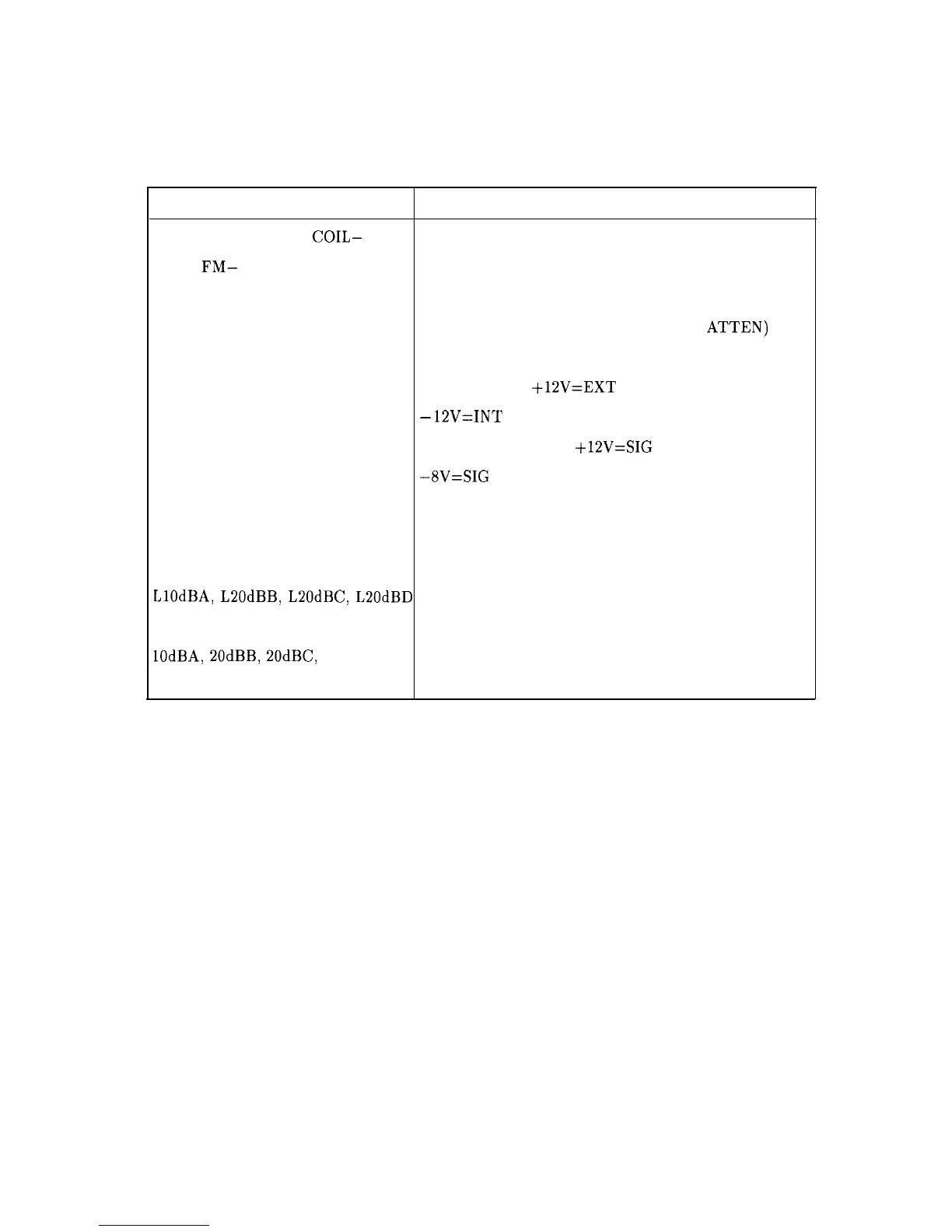
Table 11-4 lists the RF Section mnemonics shown in Figure 11-5 and provides a brief
description of each.
Table 11-4. RF Section Mnemonic Table
Mnemonic Description
MAIN COIL+, MAIN
COIL-
YTO Main Coil Tune Signal
FM+,
FM-
YTO FM Coil Tune Signal
LO SENSE LO Amplitude Sense Voltage
LEVEL ADJUST LO Amplitude Adjustment Voltage (PIN
ATTEN)
GATE BIAS LODA Gate Bias Voltage
XMX External Mixer;
+lZV=EXT
MIX
-
12V=INT
MIX
SID
SIG ID Oscillator ON
+12V=SIG
ID OFF
-8V=SIG
ID ON
PIN DIODE SWITCH PIN Diode Switch Control For 2ND Conv. IF Output
RFGAIN Voltage to Control Gain of Flatness Comp. Amps.
RFGAIN 1 and RFGAIN 2
Currents to Drive PIN Diodes in Flatness Comp. Amps.
LlOdBA, L20dBB,
LZOdBC,
L20dBD Control Lines to Set Attenuator Sections A, B, C, and D
to Attenuate Position (Active Low)
lOdBA, 20dBB, 20dBC, 20dBD Control Lines to Set Attenuator Sections A, B, C, and D
to Attenuate Position (Active High)
RF Section 1 I-17