--m--m--m--------
All
r;;7
1ST
LO DISTRIBUTION ,
1
YTO
J4
’
F
1
JZ
1
SAMPLER
1ST
MIXER OUT OUT -9
13 TOTO -2
16
dh
dBM
J3
I
I
1ST
LO OUT 14.5 TO 18.5
dBm
t
I
-----
J
SCHEMAT I C
AS V INCREASES
__I
A7 OUTPUT INCREASES
3OF5
,m”v”m”-------
REF VOLTAGE
L
SK1115
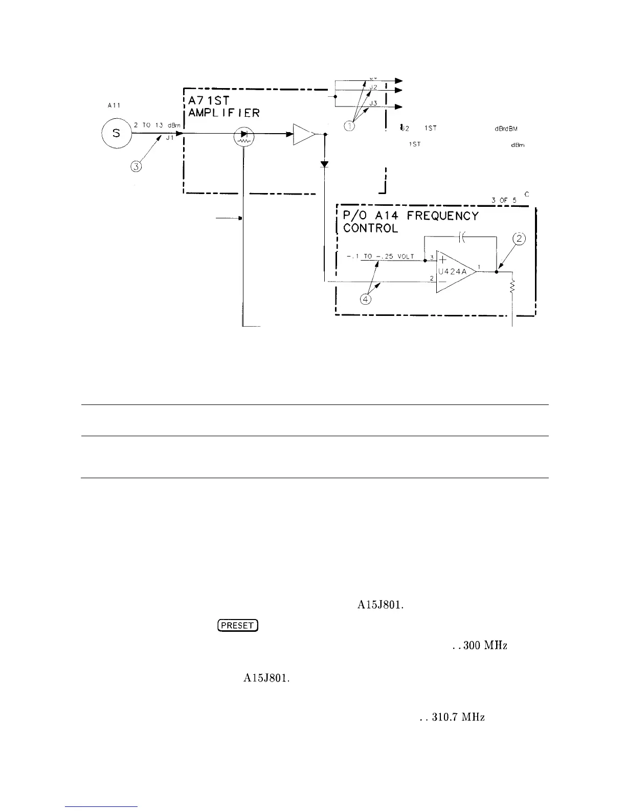
Figure 11-2. A7 LODA Drive
Al5 RF Assembly
Note
The block diagrams for the Al4 and Al5 assemblies are located in Chapter 10,
Synthesizer Section.
Confirming a Faulty Third Converter
1. Perform the IF Input Amplitude Accuracy performance test in the HP 8560A Installation
and Verification Manual if Option 002 is not present. This exercises most of the third
converter.
2. If the performance test fails or Option 002 is present, perform the External Mixer
Amplitude adjustment in Chapter 2 of this manual.
3. If adjustment cannot be made, disconnect W35 from A15J801.
4. On the HP 8560A press
(PRESET)
and set the controls to the following settings:
CENTER FREQ. . . . . . . . . . . . . . . . . . . . . . . . . . . . . . . . . . . . . . . . . . . . .
..300MHz
SPAN
. . . . . . . . . . . . . . . . . . . . . . . . . . . . . . . . . . . . . . . . . . . . . . . . . . . . . . . . . . . . 0 Hz
5. Connect a signal generator to A15J801.
6. Set the signal generator to the following settings:
Frequency
. . . . . . . . . . . . . . . . . . . . . . . . . . . . . . . . . . . . . . . . . . . . .
..310.7MHz
CW
Power
. . . . . . . . . . . . . . . . . . . . . . . . . . . . . . . . . . . . . . . . . . . . . . . . . . . . . . . . -28 dBm
11-10 RF Section