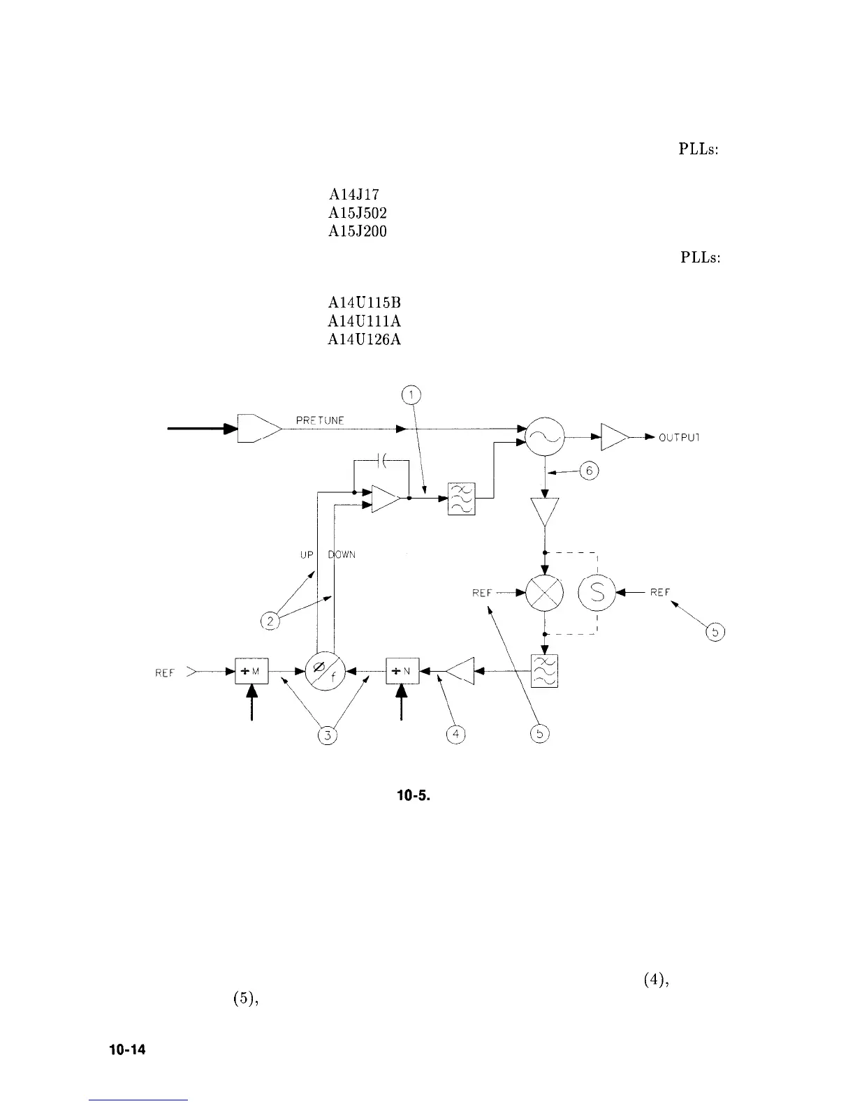
1. The loop integrator’s output voltage (1) should be attempting to tune the oscillator to the
correct frequency.
a. The voltage at (1) should increase as the frequency increases on the following PLLs:
YTO PLL
A14J17 pin 1 (YTO LOOP ERROR)
Reference PLL
A15J502 pin 3 (LO3 ERR)
Sampler PLL
A15J200 pin 13 (OFL ERR)
b. The voltage at (1) should
increase as the frequency decreases on the following PLLs:
Main Roller PLL
A14U115B pin 7 (MAINSENSE)
Offset Roller PLL
A14UlllA
pin 1 (OFFSENSE)
Transfer Roller PLL
A14U126A pin 1 (XFRSENSE)
OUTPUl
SK1 105
Figure
10-5.
Unlocked PLL
2. If the integrator’s output voltage changes in the manner described in step 1, the problem
is external to the PLL. For example, the pretune DAC could be faulty. If the integrator’s
output voltage appears incorrect, confirm that the pulses out of the phase detector (2) are
attempting to tune the oscillator in the correct direction.
3. If the phase detector’s output is bad, check the inputs to the detector (3). One input
should be higher in frequency than the other; this should match the phase detector
outputs.
4. Confirm proper power levels for the signals at the input to the “N” dividers
(4),
the
reference input
(5))
and the loop’s feedback path (6).
lo-14
Synthesizer Section