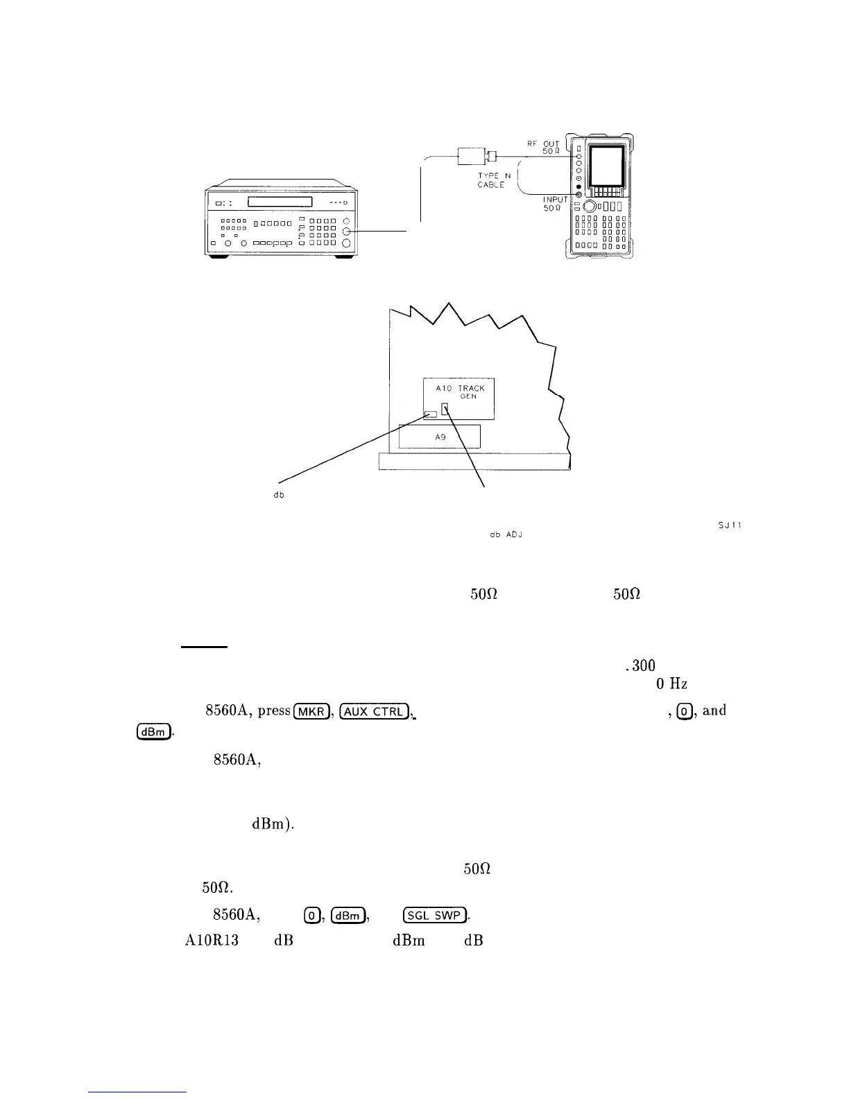
9. Tracking Generator Power Level Adjustments
2.
Connect the Type N cable between the RF OUT
500
and RF INPUT
50R
connectors on
the HP 8560A.
3.
Press (PRESET) on the HP 8560A and set the controls as follows:
4.
CENTER FREQ
. . . . . . . . . . . . . . . . . . . . . . . . . . . . . . . . . . . . . . . . . . . . .
.300 MHz
SPAN
. . . . . . . . . . . . . . . . . . . . . . . . . . . . . . . . . . . . . . . . . . . . . . . . . . . . . . . . . . .
OHz
On the HP
8560A,press
(K),(AUXCTRTI),
TRACKING GENRATOR, SRC PWR ON
,@,and
m.
5.
On the HP 8560A, press MORE 1 OF 3 , TRACKING PEAK. Wait for the “PEAKING”
message to disappear.
6.
Zero and calibrate the measuring receiver/power sensor combination in log mode (power
levels readout in
dBm).
Enter the power sensor’s 300 MHz Cal Factor into the measuring
receiver.
7.
Disconnect the Type N cable from the RF OUT
50R
and connect the power sensor to the
RF OUT
5Ofl.
8.
On the HP 8560A, press
@,
m,
and
(mSWP).
MEASURING RECEIVER
mj
SPECTRUM ANALYZER
POWER SENSOR
-10
db
ADJ
\
SJll
0
db
ADJ
Figure 2-12. Tracking Generator Power Level Adjustments Setup and Adjustment Locations
9. Adjust
AlOR
-10 dB ADJ for a 0
dBm
+/-.05 dB reading on the measuring receiver.
Adjustment Procedures 2-43