A9 Input Attenuator
Removal
1. Disconnect W34 at A15A2J1, and place the analyzer upside-down on the work bench.
2. Remove W41 and disconnect W44 from the attenuator.
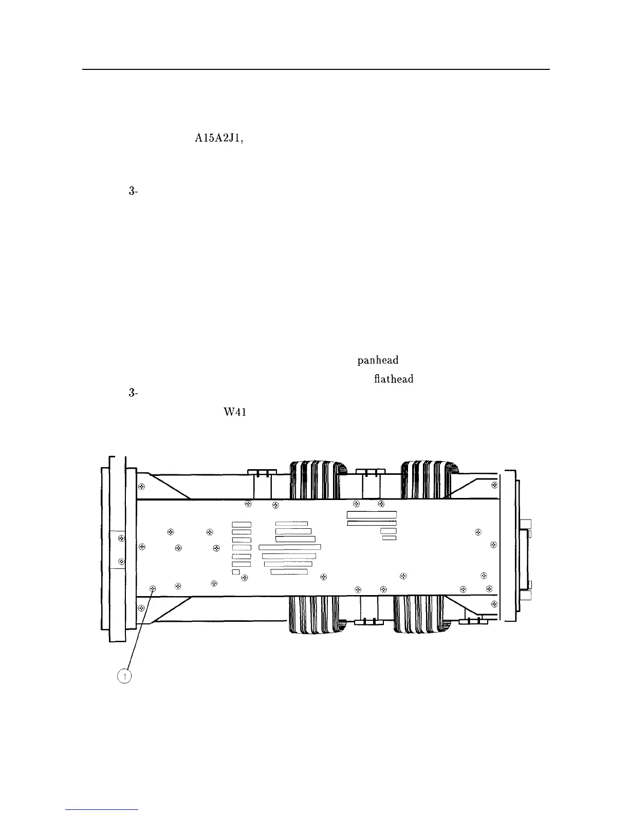
3. Remove screw (1) securing the attenuator to the front-frame center support. See
Figure
3-
15.
4. Remove screw (1) securing the A9 Input Attenuator to the right side frame. See
Figure 3-16.
5. Remove the attenuator and disconnect the attenuator ribbon cable.
Replacement
1. Connect the attenuator-control ribbon cable to the A9 Input Attenuator.
2. Place the A9 Input Attenuator into the analyzer with the A9 mounting brackets resting
against the front-frame center support and the right side frame. Use caution to avoid
damaging any cables.
3. Attach the attenuator to the center support with one
panhead
screw (1). See Figure 3-15.
4. Attach the attenuator to the right side frame, using one
flathead
screw (1). See
Figure
3-
16.
5. Connect semirigid cables
W4l
and W44 to the attenuator assembly. Connect opposite end
of W41 to the front frame.
I
0
ii
0
Figure 3-18. A9 Mounting Screws at Right Frame
3-30 Assembly Replacement