ATTEN
10dB
RL OdBm
10dB,’
BIRoKEN
JSYMME~~TRY
1
CENTER
300.0000MHz
SPAN 100
0kHz
*RBW
3.0kHz
VBW
3.0kHr
SWP 70ms
SK184
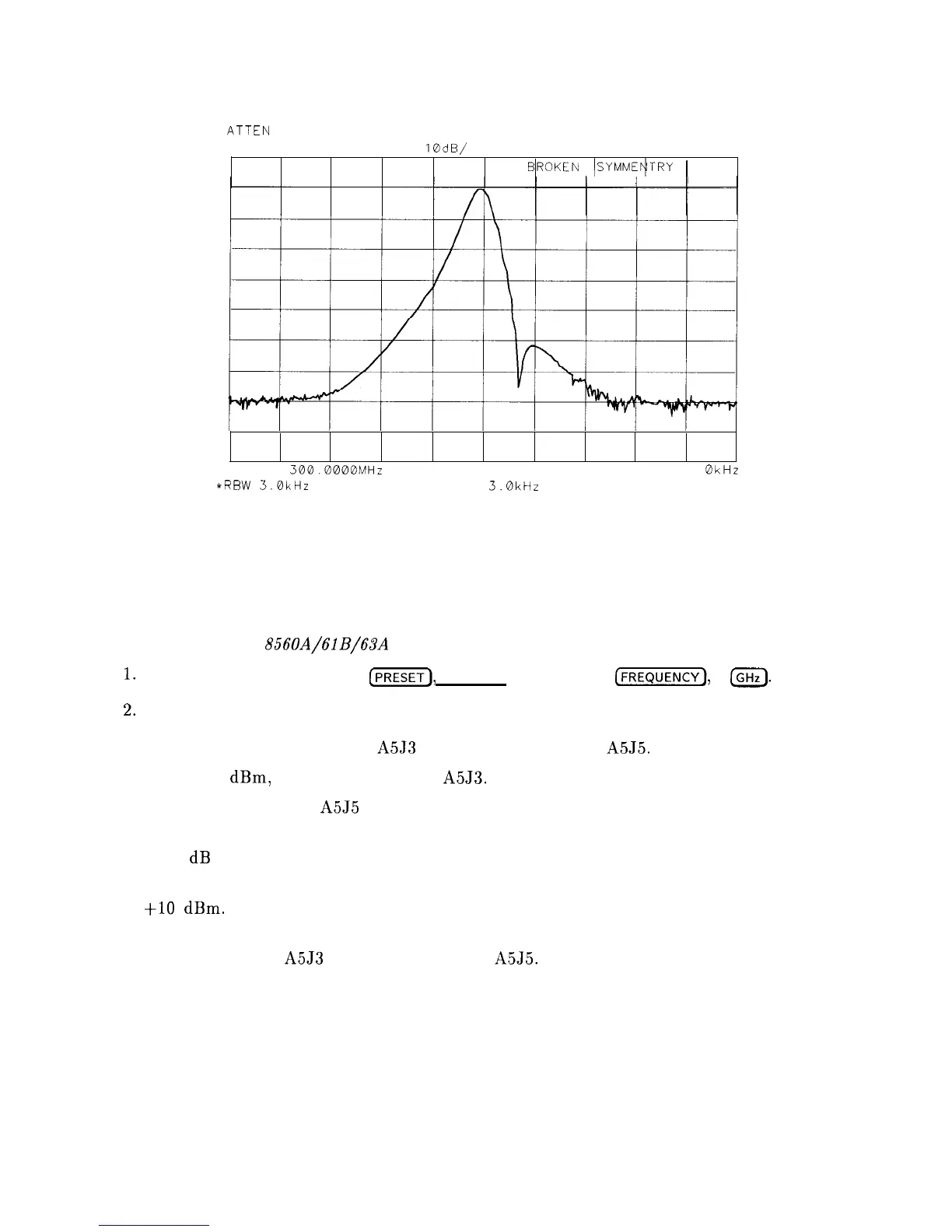
Figure 8-15. Faulty Crystal Symmetry
Step Gains
Refer to function blocks B, H, and I of A5 IF Filter Schematic Diagram (sheets 1 of 3 and
2 of 3) in the HP
856OA/61B/63A
Spectrum Analyzer Component Level Information binder.
I.
On the spectrum analyzer, press
(-1,
(SPAN), ZERO SPAN ,
(w),
1
IGHz).
2.
Press (CAL), IF ADJ OFF.
3. Disconnect W29 (coax 7) from A5J3 and W27 (coax 3) from A5J5.
4. Inject a -5
dBm,
10.7 MHz signal into A5J3.
5. Monitor the output of A5J5 with another spectrum analyzer.
6. Simultaneously decrease the signal generator output and spectrum analyzer reference level
in 10 dB steps.
7. At each step, the signal displayed on the other spectrum analyzer should be close to
+lO
dBm.
(More subtle IF gain problems might require smaller signal generator and
reference level steps.)
8. Reconnect W29 to A5J3 and W27 (coax 3) to
A5J5.
IF Section 8-33