Note
Because the Cal Oscillator circuitry on the A4 assembly is such an integral
part of the IF adjustment, always check this assembly first, before checking
the rest of the IF Section. A faulty Cal Oscillator can cause many apparent
“faults” in the rest of the IF Section.
Troubleshooting Using the TAM
When using Automatic Fault Isolation, the TAM indicates suspected circuits that need to be
manually checked. Use Table 8-l to locate the manual procedure.
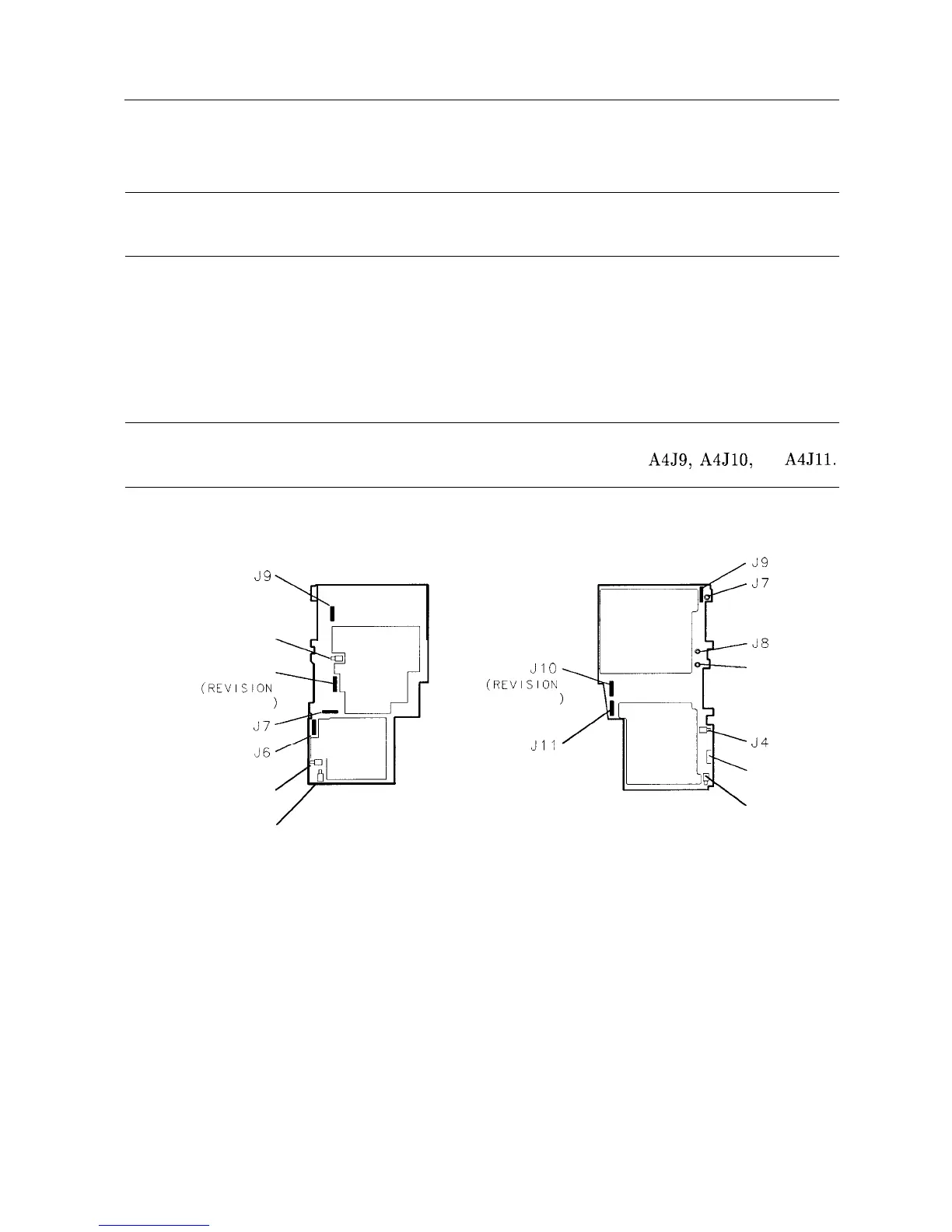
Table 8-2 lists assembly test connectors associated with each Manual Probe Troubleshooting
test. Figure 8-l illustrates the location of A4 and A5 test connectors. Figure 8-2 illustrates
the levels and paths through the IF Section.
Note
HP 85629B Test and Adjustment Modules with firmware revisions A through
F cannot make valid measurements on test connectors
A4J9,
A4J10, or
A4Jll.
39
J5
J8
(REVISION
CONNECTOR
37
J4
A5 IF
J3
/
JIO
(REVISION
CONNECTOR
Jll
A4 LOG AMP
/Jg
37
J5
34
J6
J3
SK170
Figure 8-1. A4 and A5 Test Connectors
IF Section 8-3