Caution
Use of an active probe, such as an HP 85024A, with another spectrum
analyzer is recommended for troubleshooting the RF circuitry. If an HP
1120A Active Probe is being used with a spectrum analyzer, such as the HP
8566A/B,
HP 8569A/B
and the HP
8562A/B,
h
aving dc coupled inputs, either
set the active probe for an ac coupled output or use a dc blocking capacitor
(HP 11240B) b
e
tween
the active probe and the spectrum analyzer input.
Troubleshooting Using the TAM
When using Automatic Fault Isolation, the TAM indicates suspected circuits that need to be
manually checked. Use Table 11-2 to locate the manual procedure.
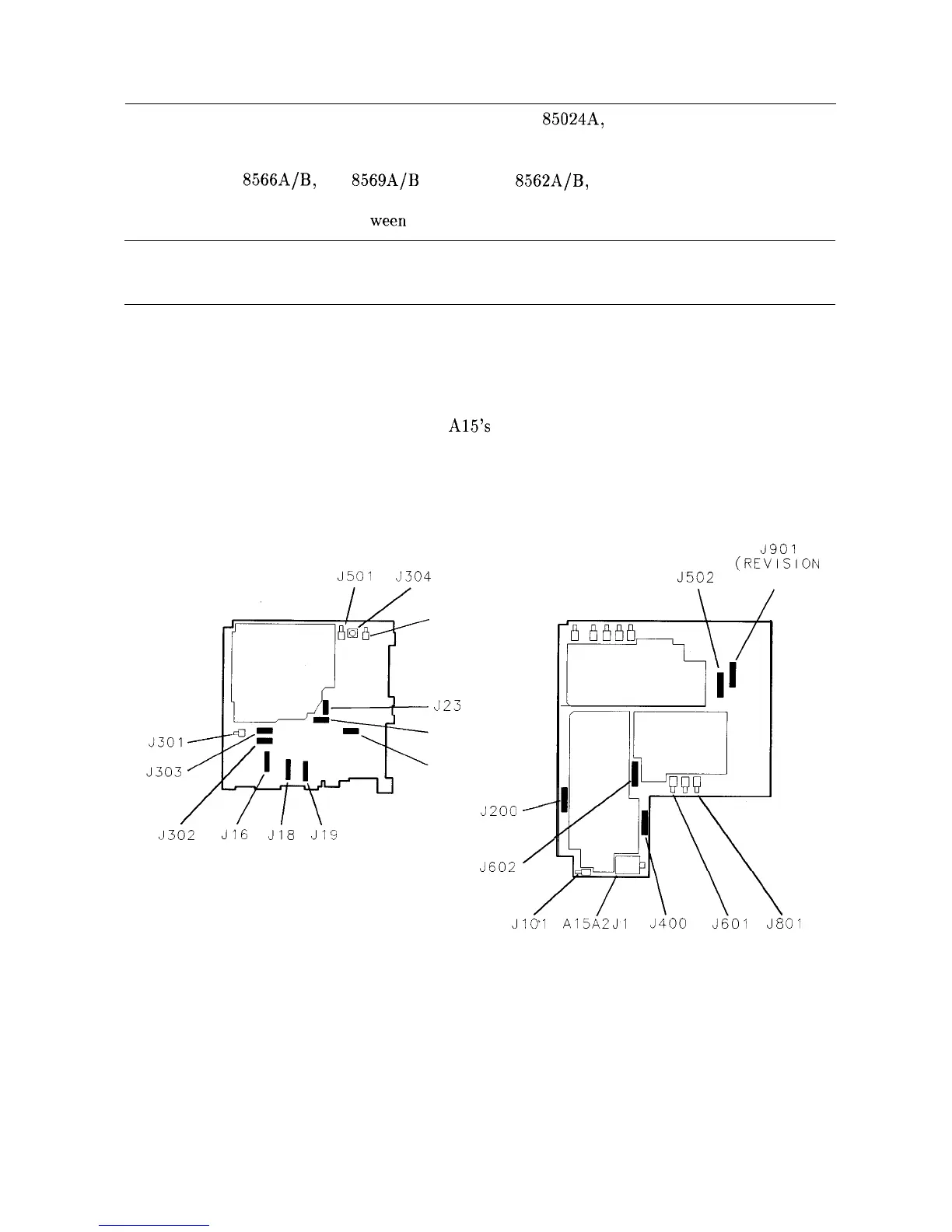
Table 11-l lists assembly test connectors associated with each Manual Probe Troubleshooting
test. Figure 11-l illustrates the location of
A15’s
test connectors.
Al4
FREQUENCY
CONTROL
J5Ol
J304
J302
J16
J18
.J19
(REVISION
CONNECTOR)
J7
J23
J17
J15
JZOO
’
J602
/
Al5
RF
3901
(REVISION
J502
CONNECTOR)
Jlo’l
A15AZJl
J400
3601
J801
SK1114
Figure 11-l. Al4 and Al5 Test Connectors
11-2 RF Section