Procedure 14. W3 Line Switch Cable
6. Attach the line-switch assembly into the front frame using the captive
panhead
screw. Be
sure to connect the line-switch grounding lug with the screw.
SK152
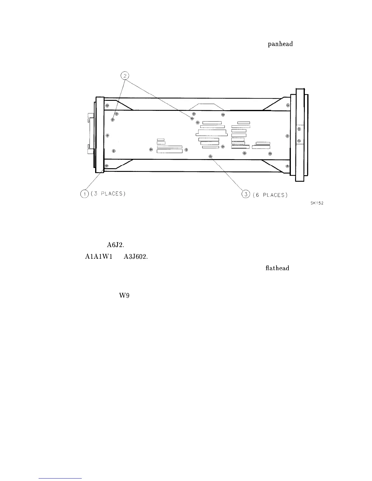
Figure 3-27. Side Frame Mounting Screws
7. On the top side of the analyzer, redress W3.
8. Connect W3 to A6J2. Dress W3 into the slotted opening in the deck.
9. Connect
AlAlWl
to A3J602.
10. Secure the power-supply cover shield to the power supply using three
flathead
screws. One
end of the cover fits into a slot provided in the rear-frame assembly.
11. Place W3 and the other cable assemblies between the CRT assembly and the power
supply cover so the W9 wires are below the surface of the power-supply cover.
12. Fold up the A2, A3, A4, and A5 assemblies into the analyzer as described in Procedure 5,
“A2, A3, A4, and A5 Assemblies Replacement,” steps 5 through 10.
13. Fold up Al4 and Al5 assemblies as described in Procedure 9, “Al4 and Al5 Assemblies
Replacement,” steps 3 through 5.
14. Replace the analyzer’s cover assembly.
15. Connect the line-power cord and switch the analyzer’s power on. If the analyzer does not
operate properly, turn off the analyzer power, disconnect the line cord, and recheck the
analyzer.
Assembly Replacement 3-49