8. If the reset pulses are absent, troubleshoot the Peak Detector Reset circuitry.
9. If the reset pulses are present, check the gate of
Q207.
The pulses should be positive-going
from -12.7 V to -1.35 V.
10. The peak detector can be made into a unity gain amplifier by shorting the cathode of
CR203 to the anode of CR204. If the peak detector functions normally as a unity gain
amplifier, suspect
Q208
or CR203 or CR204.
Peak Detector Reset
See function block R of A3 Interface Assembly Schematic Diagram (sheet 4 of 6).
1. Press
(PRESET]
on the HP 8560A and set the controls as follows:
CENTER FREQ. . . . . . . . . . . . . . . . . . . . . . . . . . . . . . . . . . . . . . . . . . . . .
..300MHz
SPAN. . . . . . . . . . . . . . . . . . . . . . . . . . . . . . . . . . . . . . . . . . . . . . . . . . . . . . . . . . . . 0 Hz
SWEEP TIME. . . . . . . . . . . . . . . . . . . . . . . . . . . . . . . . . . . . . . . . . . . . . . . . . . . . . . 5s
DETECTOR MODE . . . . . . . . . . . . . . . . . . . . . . . . . . . . . . . . . . . . . . . . . POS PEAK
2. Check that HHOLD
(A3U526 pin 11) has 18 ps wide pulses every 128
pus.
3. Check that HODD (U408 pin 5) is a square wave with a period of 16.7 ms
(2 x sweep
time/600).
4. Check
LPOS-RST
(U422 pin 4) for 200 ns low-going pulses every 128
pus.
5. Check LNEG_RST (A3U422 pin 12) for 200 ns low-going pulses every 128
ps.
6. Set the detector mode to NORMAL and check that LNEG_RST (A3U422 pin 12) has two
pulses spaced 40
pus
apart and then a single pulse approximately 88 ps from the second
pulse.
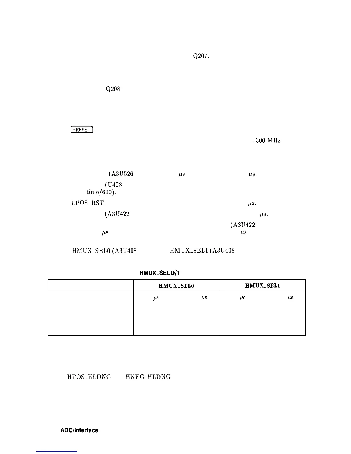
7. Check
HMUXSELO
(A3U408 pin 3) and
HMUXSELl
(A3U408 pin 9) according to
Table 7-8.
Table 7-8. HMUX-SELO/l Versus Detector Mode
Detector Mode
HMUX-SELO
NORMAL
40
ps
pulse every 128
ps
SAMPLE
H
POS PEAK
H
NEG PEAK
L
HMUX-SELl
40
ps
pulse every 128
ps
H
L
H
Rosenfell Detector
See function block S of A3 Interface Assembly Schematic Diagram (sheet 4 of 6).
If both
HPOS-HLDNG
and
HNEG-HLDNG
are high during the same bucket,
HROSENFELL will also be set high. This indicates that the video signal probably consists of
noise, since it rose and fell during the same period. The HROSENFELL signal is valid only
when the NORMAL (
rosenfell) detector mode is selected.
7-18
ADC/lnterface
Section