8. First LO Distribution Amplifier Adjustment
Assembly Adjusted
Al4 Frequency Control Assembly
Related Performance Test
First LO OUTPUT Amplitude
Description
The gate bias for the A7 LO Distribution Amplifier is adjusted to the value specified on A7.
LO AMPTD is adjusted so that the LO SENSE voltage is 6 mV more negative than the value
specified on the A7 LODA label.
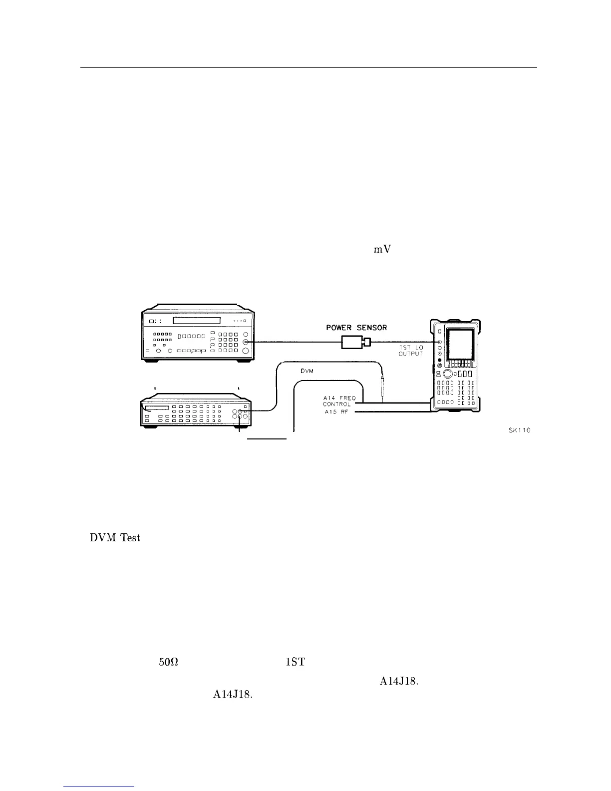
MEASURING RECEIVER
DIGITAL VOLTMETER
SPECTRUM
ANALYZER
DVM TEST LEADS
SKI10
Figure 2-11. First LO Distribution Amplifier Adjustment Setup
Equipment
Measuring Receiver .............................................. HP 8902A
DVM .......................................................... HP 3456A
Power Sensor ................................................... HP 8485A
DVMTest
Leads ................................................ HP 34118A
Adapters
Type N (f) to APC (m) . . . . . . . . . . . . . . . . . . . . . . . . . . . . . . . . . . . . . . . . . . . 1250-1750
Procedure
1. Set the HP 8560A (LINE) switch off and disconnect the line cord. Remove the cover and
fold down the Al5 RF and Al4 Frequency Control assemblies. Reconnect the line cord.
2. Remove the
500
termination from the
1ST
LO OUTPUT.
3. Connect the positive lead of the DVM probe to pin 15 of A14J18. Connect the DVM
ground lead to pin 6 of A14J18. See Figure 2-11.
2-40 Adjustment Procedures