4. IF Amplitude Adjustments
A5 IF
A4 LOG AMP
R445
J4’
/
Jll
JIO
(REVISION
CONNECTOR)
J9
J7
R826
J2
38
J5
Jl
J4
R544
J3
R531'
SK190
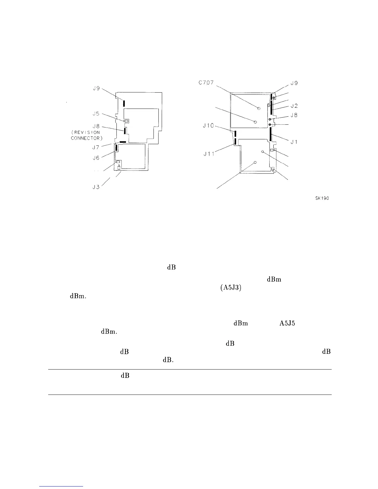
Figure 2-7. IF Amplitude Adjustment Locations
A4 Log Amp/Cal Oscillator Amplitude Adjustment
This adjustment sets the output amplitude of the A4 Log Amp/Cal Oscillator and the
absolute amplitude of the reference 15 dB attenuator.
The output of the A4 Log Amp/Cal Oscillator is adjusted so that a -55
dBm
signal
applied to the 10.7 MHz IF input on the A5 IF assembly
(A5J3)
causes a displayed signal
of -60
dBm.
The effect of this adjustment is visible only after the ADJ CURR IF STATE
sequence is complete. ADJ CURR IF STATE causes the IF gain adjustment to use the “new”
output amplitude from the A4 Log Amp/Cal Oscillator. When the adjustment sequence
is complete, the result of the adjustment should cause the -35
dBm
signal at A5J5 to be
displayed at -60
dBm.
This procedure also sets the attenuator of the reference 15
dB
attenuator so that a source
amplitude change of 50 dB combined with a spectrum analyzer reference level change of 50 dB
displays an amplitude difference of 50 dB.
Note
The 15 dB Reference Attenuator adjustment is preset at the factory and need
not be done if the entire A5 IF assembly is replaced.
2-26 Adjustment Procedures