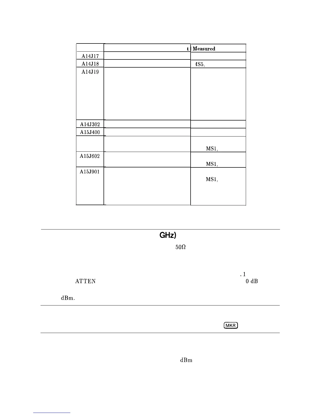
Table 11-2. TAM Tests versus Test Connectors
Connector
A14J17
A14J18
A14J19
A14J302
A15J400
A15J502
A15J602
A15J901
Manual Probe Troubleshooting Tes
Main Coil Course DAC
LODA Drive
Second Conv PIN Switch
Second Conv Mixer Bias
Second Conv Drain Bias
Second Conv Doubler Bias
Second Conv Driver Bias
First Mixer Drive Switch
First Mixer Drive DAC
Revision
IF AMP/Limiter Bias
Third LO Tune Voltage
3rd LO Driver Amp
SIG ID Collector Bias
RF Gain Control Test
Revision
External Mixer Switch
Signal ID Switch
External Mixer Bias
RF Gain Test
leasured
Signal Lines
MS3
IIS5,
MS6, MS7, MS8
MS8
MS1
MS3
MS4 .
MS5
MS7
MS6
MS7
MS6
MS3
MSl,
MS8
MS7
MSl,
MS3
MS3
MSl,
MS8
MS5, MS6
MS7
MS2
Low Band Problems (50 Hz to 2.9
GHz)
1. Disconnect all inputs from the front-panel INPUT
500
connector.
2. Set the HP 8560A to the following settings:
CENTER FREQ
. . . . . . . . . . . . . . . . . . . . . . . . . . . . . . . . . . . . . . . . . . . . . . . . . . 0 Hz
SPAN
. . . . . . . . . . . . . . . . . . . . . . . . . . . . . . . . . . . . . . . . . . . . . . . . . . . . . . . . . .
.1
MHz
INPUT
ATTEN
. . . . . . . . . . . . . . . . . . . . . . . . . . . . . . . . . . . . . . . . . . . . . . . . . . .
OdB
3. The LO feedthrough’s amplitude observed on the display should be between -6 and
-30
dBm.
Note
The marker will not PEAK SEARCH on the LO Feedthrough when in a
non-zero span. To measure the LO Feedthrough amplitude with the markers,
set the SPAN to 0 Hz and
CENTER FREQ to 0 Hz. Press
(MKR)
ON.
4. If the LO feedthrough’s amplitude is within limits, but signals are low, the RF path
following the A8 Low Band Mixer is operating properly.
5. If the LO feedthrough’s amplitude is higher than -5
dBm
(signal will be “clipped” at top
of screen) and signals are low in amplitude, suspect a defective A8 Low Band Mixer.
11-4 RF Section