6. Sampling Oscillator Adjustment
23. Set the HP 6114A Power Supply for a 21 Vdc output
50.2
V. Connect the positive supply
lead to X201 pin 1 and the negative supply lead to X201 pin 4.
24. Connect the active probe to TP201.
25. Set the HP 8560A [LINE] switch on and set the controls as follows:
CENTERFREQ
. . . . . . . . . . . . . . . . . . . . . . . . . . . . . . . . . . . . . . . . . . . .
..661MHz
SPAN
. . . . . . . . . . . . . . . . . . . . . . . . . . . . . . . . . . . . . . . . . . . . . . . . . . . . . . . . . . . 0 Hz
26. Set the HP 5343A Frequency Counter as follows:
SAMPLE RATE . . . . . . . . . . . . . . . . . . . . . . . . . . . . . . . . . . . . . . . Counterclockwise
50R--MO
SWITCH . . . . . . . . . . . . . . . . . . . . . . . . . . . . . . . . . . . . . . . . . . . . . . . .
500
10 Hz-500 MHz/500 MHz-26.5 GHz SWITCH . . . . . . . . . . . 10 Hz-500 MHz
RESOLUTION . . . . . . . . . . . . . . . . . . . . . . . . . . . . . . . . . . . . . . . . . . . . . . . . 100 kHz
27. Starting at the end of 2200 nearest X201, short the center conductor to a hole in the
ground plane with the lead of a 1
MR resistor (HP part number 0757-0059) until the
frequency counter reads 298 MHz
f4
MHz.
28. Once the proper tap has been found, solder the resistor lead to the ground plane and the
center conductor of 2200. Cut away the rest of the resistor.
29. Remove the power supply leads and the active probe.
30. Set the HP 8560A (LINE) switch off and reinstall the top shield. Set the
m
switch on.
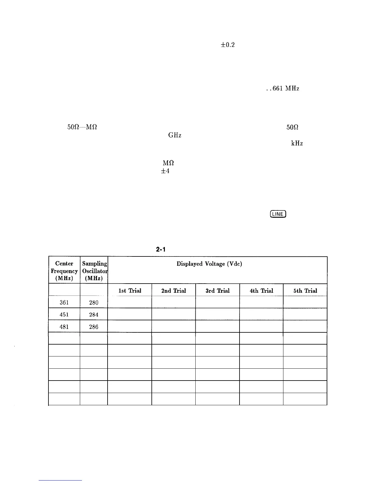
31. Repeat the procedure beginning at step 2 for the remaining center frequencies listed in
Table 2-11.
Table
2-l
1. Sampling Adjustments
511
288
541
290
571
292
601
294
631
296
661
298
2-36 Adjustment Procedures