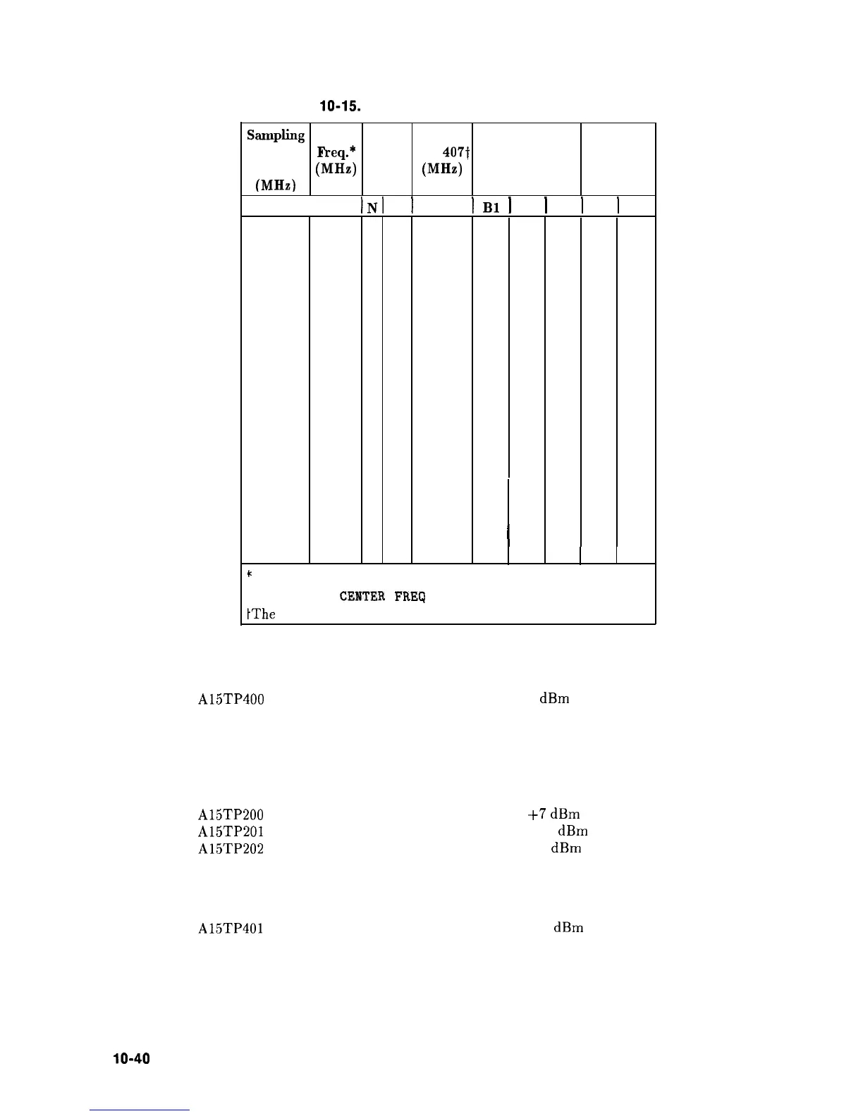
Table 10-15. Sampling Oscillator PLL Divide Ratios
!klplitlg
Oscillator
Freq.
(MHz)
Center Divide TP 406,
Freq.*
Ratios TP 4071
(MHz) (MHz)
N Control
Lines
M Control
Lines
280.0
389.5
8
4
2.5
high highhigh high low
282.5
427.0
7
4
2.5
low highhigh high low
284.0
449.5
8
5
2.0
high high
high low high
285.0
464.5
6
4
2.5
high lowhigh high low
286.0
479.5
7
5
2.0
low high
high low high
287.5
502.0
5
4
2.5
low lowhigh high low
288.0 509.5
6
5
2.0
high lowhigh low high
290.0 539.5
5 5
2.0
low lowhigh low high
292.0 569.5
4
5
2.0
high highlow low high
292.5
577.0
3
4
2.5
low high
low high low
294.0 599.5
3
5
2.0
low highlow low high
295.0
614.5
2
4
2.5
high low
low high low
296.0 629.5
2
5
2.0
high low
low low high
297.5
652.0
1
4
2.5
low
low
low high low
298.0 659.5
1
5
2.0
low
1
low low low high
I
INI
M
1
1
Bl
1
B2
I
B3
I
B4
I
B5
c
To set the Sampling Oscillator to a desired frequency, set span
to 0 Hz and CENTER
FREQ
to the value listed in the table.
tThe
signals at TP406 and TP407 are TTL levels.
10. Measure the 280 MHz loop-feedback signal at the following test point:
A15TP400
0
dBm
11. If the feedback signal is not near the indicated power, measure the signal at the following
test points on the feedback path. Refer to function blocks AD, AG, and AH of Al5 RF
Schematic (sheet 3 of 3).
A15TP200
A15TP201
A15TP202
+7
dBm
+17
dBm
+8
dBm
12. Measure the 20 MHz loop-IF signal at the following test point:
A15TP401
-6
dBm
13. If the IF signal is not near the indicated power, troubleshoot the loop mixer (function
block AI).
lo-40
Synthesizer Section