6. Sampling Oscillator Adjustment
12. Record the displayed voltage in Table 2-11 as the displayed voltage for the sampling
oscillator frequency of 288 MHz.
13. Press
(m)
on the HP 8560A. Use the step keys to set the analyzer center
frequency to the frequencies listed in Table 2-11. At each listed frequency, record the
’
displayed voltage in the table.
14. If the difference between the maximum and minimum voltages is less than 0.50 V, and all
voltage readings are between
to.5
and
t2.5
Vdc, proceed to step 19.
15. Locate the center frequency at which the voltage is lowest. Use the
II]
and
II]
keys to set
the HP 8560A to this frequency.
16. Readjust SMPL MATCH 1 to set the displayed voltage to 0.8
$0.1
Vdc.
17. Move the positive DVM test lead to A15J400 pin 3.
18. Set the HP 8560A center frequency to 511 MHz.
19. Readjust A15R237 SMPL PWR ADJ if necessary, until the voltage at A15J400 pin 3 is
-0.5 to -2.5 Vdc and the voltage at A15J400 pin 1 is -0.5 to i-2.5 Vdc.
20. Disconnect the DVM probes from A15J400.
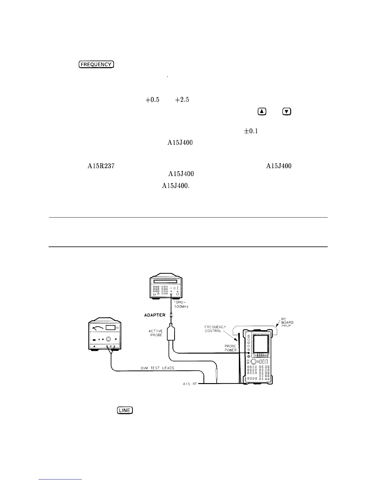
Coarse-Tune Adjustment
Note
This adjustment should be necessary only if the coaxial resonator 2200 has
been replaced or if there was insufficient range in the Sampling Oscillator
Fine-Tune Adjustment.
FREQUENCY
COUNTER
POWER
SUPPLY
A14
SPECTRUM
ANALYZER
Figure 2-9. Coarse-Tune Adjustment Setup
SK18
21. Set the HP 8560A
m
switch off and remove the top shield over the sampling oscillator.
Connect the equipment as shown in Figure 2-9.
22. Remove any existing shorts from the exposed center-conductor of coaxial resonator 2200
to the ground plane.
Adjustment Procedures
2-35