Sweep Generator Circuit
The Sweep Generator operates by feeding a constant current from DAC U307 into an
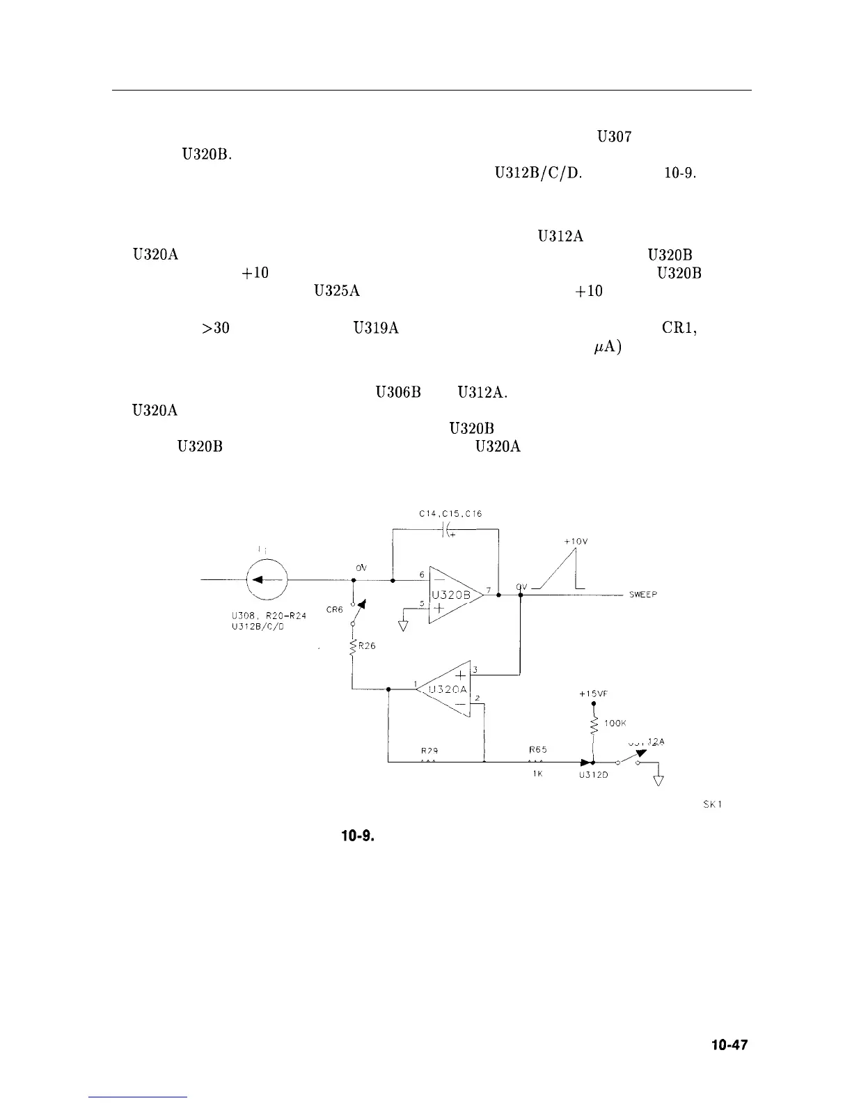
integrator, U320B. See function block K of Al4 Frequency Control Schematic (sheet 2 of 5).
This current is scaled by resistors R20 through R24 and
U312B/C/D.
See Figure
10-9.
The
capacitors used in the integrator depend on the sweep-time range; smaller-value capacitors
provide faster sweep times.
The integration is initiated by HSCAN going high. This opens U312A which places the output
of U320A near -15 Vdc, turning CR6 off and allowing the output of integrator
U320B
to
ramp from 0 V to
+lO
Vdc. The analyzer’s ADC
(
via the scan ramp attenuator
U320B
pin
7) monitors the scan ramp at U325A pin 1. When the ramp reaches
+lO
V (for single-band
sweeps), HSCAN is brought low and the integration ends. During normal non-fast-zero spans
(sweep times
>30
ms), comparators U319A and B are high. This turns on diodes
CRl,
CR2,
CR3, and CR4. Note that the integrating current (maximum value 236
PA)
actually flows
backwards through diodes CR3 and CR4.
During retrace, HSCAN is low, closing U306B and U312A. See Figure 10-10. The output
of U320A tries to go high, turning CR6 on and sourcing current through R26. This current
discharges the capacitors in the integrator, forcing
U320B
pin 7 toward 0 Vdc. Ultimately, the
output of U320B will be brought and held to 0 V by U320A supplying a current equal to that
which is sunk by the current source.
CURRENT SOURCE
U308,
R20-R24
U312B/C/D
750R
R26
+1ov
+15VF
1
iOOK
U31
12A
R65
526K
IK
SK1
109
Figure
10-9.
Simplified Sweep Generator
Synthesizer Section lo-47