7. If a correct signal is seen at A15TP201 but the signal at
A15TPlOl
is wrong, proceed as
follows:
.
Use an oscilloscope to measure the signals at the following test points:
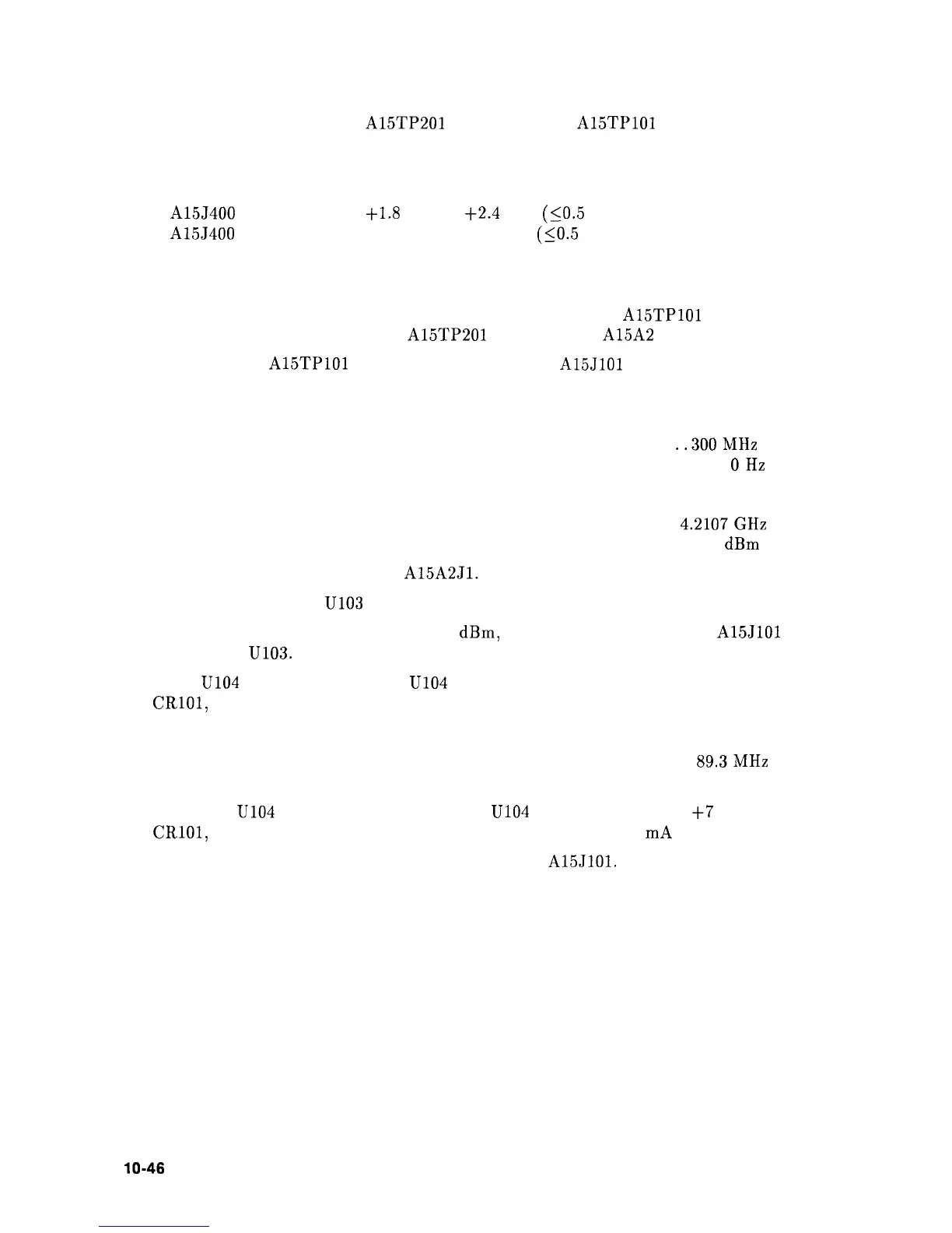
A15J400 pin 1
t1.8
Vdc to
t2.4
Vdc
(LO.5
Vp-p variation)
A15J400 pin 3
-1.8 Vdc to -2.4 Vdc
(SO.5 Vp-p variation)
If these levels are wrong, perform the “Power and Sampler Match Adjustments” in the
Sampler Oscillator Adjustment procedure. Refer to Chapter 2.
If adjusting the Sampler Match does not bring the signal at
Al5TPlOl
within
specification when the signal at A15TP201 is correct, the A15A2 Sampler is defective.
8. If the signal at
A15TPlOl
is correct, but the signal at
A15JlOl
is wrong, the fault lies in
the Sampler IF circuitry. Continue with the following steps.
9. Set the HP 8560A to the following settings:
CENTER FREQ
. . . . . . . . . . . . . . . . . . . . . . . . . . . . . . . . . . . . . . . . . . . .
..300MHz
SPAN
. . . . . . . . . . . . . . . . . . . . . . . . . . . . . . . . . . . . . . . . . . . . . . . . . . . . . . . . . . .
OHz
10. Set a microwave source to the following settings:
Frequency
. . . . . . . . . . . . . . . . . . . . . . . . . . . . . . . . . . . . . . . . . . . . . . . . .
4.2107GHz
Amplitude
. . . . . . . . . . . . . . . . . . . . . . . . . . . . . . . . . . . . . . . . . . . . . . . . . . . . -5
dBm
11. Connect the microwave source to
A15A2Jl.
12. Measure the signal at
U103
pin 1 using an active probe/spectrum analyzer combination.
13. If a 94.7 MHz signal, approximately -14
dBm,
is present, but the signal at
A15JlOl
is
low, suspect U103.
14. When
U104
pin 3 is at TTL low,
U104
pin 6 should near -15 Vdc and PIN diodes
CRlOl,
CR102, and CR103 should be reverse-biased.
15. Set HP 8560A to the following settings:
CENTER FREQ
. . . . . . . . . . . . . . . . . . . . . . . . . . . . . . . . . . . . . . . . . . . . .
89.3MHz
SPAN
. . . . . . . . . . . . . . . . . . . . . . . . . . , . . . . . . . . . . . . . . . . . . . . . . . . . . . . . . . . 0 Hz
16. Check that
U104
pin 3 is at a TTL high and
U104
pin 6 is greater than
+7
V. PIN diodes
CRlOl,
CR102, and CR103 should all be turned on with about 7
mA
of forward current.
17. Disconnect the power splitter and reconnect W32 to
A15JlOl.
lo-46 Synthesizer Section